| Home | SW Projects | HW Projects | People | Web Links | Contact |

| Home | SW Projects | HW Projects | People | Web Links | Contact |

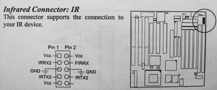
The connector is a male. Consists of 10 gold-plated pins, spaced 2.54 mm apart. This picture is taken from a FIC VA-503+ manual. Consult you own motherboard's manual for where to look for this connector.
You need a suitable female piece to connect onto this connector. Use following three wires, no more: IRRX2 (data go into PC), IRTX2 (data go from the PC outwards), GND (common ground). I recommend a shielded wire for EM compatibility.
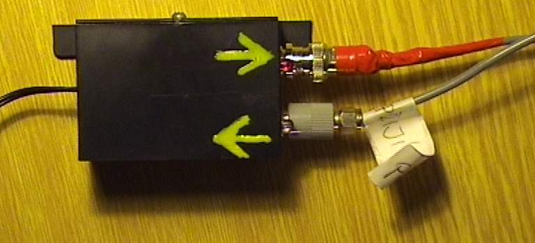
These three wires connect your PC with Ronja's IrDA interface:


you can also well see the two LED's indicating data transmission (red: TX) and reception (yellow: RX).
The internals of the IrDA interface are simple: several resistors, capacitor, LEDs and a transistor.
When using the IrDA connector, you have to click up in you BIOS that you want to have a "high, high" polarity of the IrDA signals and tell the BIOS to enable the IrDA interface in SIR mode. The connection is complete. You have to lead a bunch of wires into your PC or place some non-standard connector into some empty slot because IrDA SIR is according to my knowledge never lead out to an ordinary connector.
Note: some types of modem are not capable of operating on non-powered lines. This problem can be solved by connecting the apprpriate voltage through a suitable resistor directly to Ronja's output. The output is protected by a capacitor.