3 September 2001. Thanks to BH.
This is Appendix A of
CJCSM 6231.05a
Manual for Employing Joint Tactical Communications - Joint Communications
Security, 2 November 1998.
[12 pages.]
APPENDIX A
KIV-7 EMBEDDABLE KG-84 COMSEC MODULE
1. General. The KIV-7 is a compact COMSEC device designed
to protect digital data communications links at rates up to
512 kbps. It is compatible with the KG-84 family of
encryption devices in the secure data and OTAR modes.
Built-in key management features support the current key
distribution system and the emerging Electronic Key
Management System (EKMS). The KIV-7 fill interface is
compatible with DS-101 (data transfer device) and DS-102
(common fill) electronic keying devices, and provides
storage for up to 10 encryption keys. A removable crypto
ignition key (CIK) prevents unauthorized access and protects
the internally stored keys. The KIV-7 front panel is
pictured in Figure A-1 below.
____________________________________________________
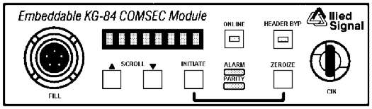 Figure A-1. KIV-7 Front Panel
____________________________________________________
2. Functional Overview. The KIV-7 encrypts and decrypts
digital data on dedicated links between communications
devices. It accepts synchronous or asynchronous, serial,
plain text data from a variety of terminal devices, encrypts
the data, modulates it if required, and produces a serial
cipher text output. The process is reversed on the receive
side. The KIV-7 operates either from internally generated
clocks or externally supplied clocking signals, including
terminal timing or station clock sources. Although normal
operation is full-duplex, it also operates in the half-
duplex and simplex (point-to-point, netted, or broadcast)
modes. In both synchronous and asynchronous data modes, the
KIV-7 operates at the following internally generated data
rates:
50 bps 600 bps 16.0 kbps 115.2 kbps
100 bps 1.2 kbps 19.2 kbps 128.0 kbps
110 bps 2.4 kbps 28.8 kbps 192.0 kbps
150 bps 4.8 kbps 32.0 kbps 288.0 kbps
200 bps 8.0 kbps 38.4 kbps
220 bps 9.6 kbps 57.6 kbps
300 bps 14.4 kbps 64.0 kbps
An external 32 x data rate clock at rates up to 1.024 MHz is
accepted in both synchronous and asynchronous modes. In
synchronous modes, an external clock signal at rates up to
512 kbps is accepted. The KIV-7HS can be externally clocked
at rates up to 1.544 Mbps.
3. RED/BLACK Interface. The KIV-7 interfaces with a
variety of communications devices at its RED and BLACK data
ports. RED interface capabilities include EIA-530 (RS-449),
RS-232, and RS-422/423. These same interface capabilities
exist on the BLACK side, along with a wireline (transformer
coupled) interface with the optional WLA-7 Wireline Adapter.
The KIV-7 accommodates both the DS-102 (KYK-13, KOI-18,
KYX-15) and DS-101 (AN/CYZ-10) fill interface standards.
Figure A-2 shows the KIV-7 interface ports along with the
typical devices with which it is interoperable.
__________________________________________________
Figure A-1. KIV-7 Front Panel
____________________________________________________
2. Functional Overview. The KIV-7 encrypts and decrypts
digital data on dedicated links between communications
devices. It accepts synchronous or asynchronous, serial,
plain text data from a variety of terminal devices, encrypts
the data, modulates it if required, and produces a serial
cipher text output. The process is reversed on the receive
side. The KIV-7 operates either from internally generated
clocks or externally supplied clocking signals, including
terminal timing or station clock sources. Although normal
operation is full-duplex, it also operates in the half-
duplex and simplex (point-to-point, netted, or broadcast)
modes. In both synchronous and asynchronous data modes, the
KIV-7 operates at the following internally generated data
rates:
50 bps 600 bps 16.0 kbps 115.2 kbps
100 bps 1.2 kbps 19.2 kbps 128.0 kbps
110 bps 2.4 kbps 28.8 kbps 192.0 kbps
150 bps 4.8 kbps 32.0 kbps 288.0 kbps
200 bps 8.0 kbps 38.4 kbps
220 bps 9.6 kbps 57.6 kbps
300 bps 14.4 kbps 64.0 kbps
An external 32 x data rate clock at rates up to 1.024 MHz is
accepted in both synchronous and asynchronous modes. In
synchronous modes, an external clock signal at rates up to
512 kbps is accepted. The KIV-7HS can be externally clocked
at rates up to 1.544 Mbps.
3. RED/BLACK Interface. The KIV-7 interfaces with a
variety of communications devices at its RED and BLACK data
ports. RED interface capabilities include EIA-530 (RS-449),
RS-232, and RS-422/423. These same interface capabilities
exist on the BLACK side, along with a wireline (transformer
coupled) interface with the optional WLA-7 Wireline Adapter.
The KIV-7 accommodates both the DS-102 (KYK-13, KOI-18,
KYX-15) and DS-101 (AN/CYZ-10) fill interface standards.
Figure A-2 shows the KIV-7 interface ports along with the
typical devices with which it is interoperable.
__________________________________________________
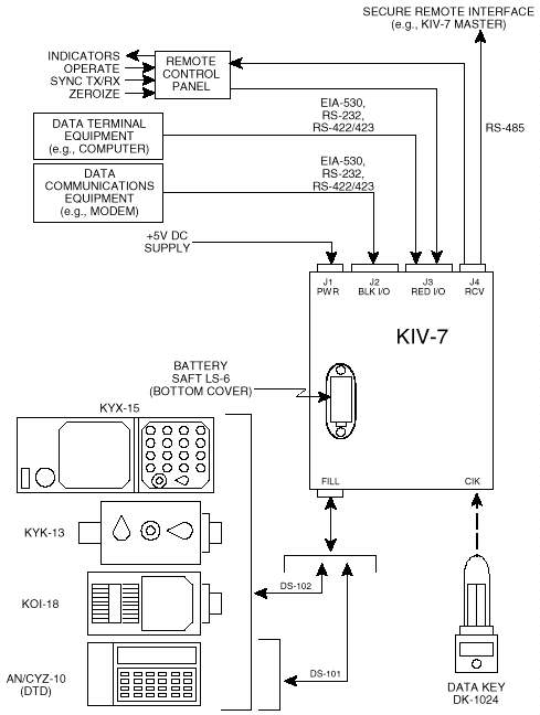 Figure A-2. KIV-7 Interconnectivity Diagram
__________________________________________________
4. RED (Plain Text) Interface. The RED input/output (I/O)
signals are available at connector J3 on the KIV-7 rear
panel, permitting direct connection of the KIV-7 with
compatible terminal equipment. The connector is a 37-pin
D-type female connector in a male shell. This interface
supports the interchange of serial digital data; associated
control information is exchanged on separate control
circuits. Table A-1 contains the pin assignments for the J3
connector, along with signal names, descriptions, and signal
direction with respect to the KIV-7. Application notes for
the RED interface follow.
___________________________________________________________
Table A-1. KIV-7 RED Interface Pinouts
___________________________________________________________
PIN # SIGNAL NAME I/O DESCRIPTION
___________________________________________________________
1 CHASSIS GND G CHASSIS GROUND
2 TXDPT-P I TRANSMIT DIGITAL PLAIN TEXT
3 RXDPT-P O RECEIVE DIGITAL PLAIN TEXT
4 PTRS-P I PLAIN TEXT REQUEST TO SEND
5 PTCS-P O PLAIN TEXT CLEAR TO SEND
6 PTDM-P O PLAIN TEXT DATA MODE
7 SIG GND G SIGNAL GROUND
8 PTRR-P O PLAIN TEXT RECEIVER READY
9 RXCLK-N O RECEIVE CLOCK
10 PTRR-N O PLAIN TEXT RECEIVER READY
11 PTTT-N I PLAIN TEXT TERMINAL TIMING
12 TXCLK-N O TRANSMIT CLOCK
13 PTCS-N O PLAIN TEXT CLEAR TO SEND
14 TXDPT-N I TRANSMIT DIGITAL PLAIN TEXT
15 TXCLK-P O TRANSMIT CLOCK
16 RXDPT-N O RECEIVE DIGITAL PLAIN TEXT
17 RXCLK-P O RECEIVE CLOCK
18 PTLL-P I PLAIN TEXT LOCAL LOOPBACK
19 PTRS-N I PLAIN TEXT REQUEST TO SEND
20 PTTR-P I PLAIN TEXT TERMINAL READY
21 PTRL-P I PLAIN TEXT REMOTE LOOPBACK
22 PTDM-N O PLAIN TEXT DATA MODE
23 PTTR-N I PLAIN TEXT TERMINAL READY
24 PTTT-P I PLAIN TEXT TERMINAL TIMING
25 PTTM-P O PLAIN TEXT TEST MODE
26 NC NC SPARE
27 SIG GND G SIGNAL GROUND
28 +5V RED O +5V TIE-OFF (RED ONLY)
29 RALMIND-P O RED ALARM INDICATOR
30 STP PUL-P O STEP PULSE
31 SYNCTX-P I SYNC COMMAND TRANSMIT
32 PTMON-P O PLAIN TEXT MONITOR
33 SYNCRX-P I SYNC COMMAND RECEIVE
34 PTMON-N O PLAIN TEXT MONITOR
35 RMTOPER-P I REMOTE OPERATE
36 -6V RED O -6V TIE-OFF (RED ONLY)
37 RMTZERO-N I REMOTE ZEROIZE
___________________________________________________________
a. Pins 1 through 25 of the DB-37 connector conform to
the circuit assignments specified in EIA-530. The elec-
trical characteristics of these circuits, however, are
selectable via the KIV-7 front panel menus. The RED
interface may be programmed for standard EIA-530, standard
RS-232, or a hybrid RS-422/423 which is similar to the
RS-449 interface of the KG-84C. EIA-530 will replace RS-449.
Pins 26 through 37 are assigned KIV-7 specific functions
with fixed electrical characteristics.
b. When standard EIA-530 is selected, the data, timing,
and control signals fall into two categories. Category I
signals are balanced and conform to the electrical charac-
teristics specified in RS-422. Category I signals include:
Transmit Digital Plain Text
Receive Digital Plain Text
Transmit Clock
Receive Clock
Plain Text Terminal Timing
Plain Text Request to Send
Plain Text Clear to Send
Plain Text Data Mode
Plain Text Receiver Ready
Plain Text Terminal Ready
Category II signals are unbalanced and conform to the elec-
trical characteristics specified in RS-423. Category II
signals include:
Plain Text Local Loopback
Plain Text Remote Loopback
Plain Text Test Mode
c. When standard RS-232 is selected, all data, timing,
and control signals are unbalanced and conform to the
electrical, mechanical, and circuit function characteristics
specified in the RS-232 standard. In addition, the
interface meets the electrical characteristics of RS-423.
When this interface is selected, input signals TXDPT-N,
PTRS-N, PTTT-N, and PTTR-N must be tied to signal ground.
Output signals RXDPT-N, PTCS-N, PTDM-N, PTRR-N, RXCLK-N, and
TXCLK-N are not active and should not be connected.
d. When hybrid RS-422/423 is selected, data and timing
signals are balanced and conform to the electrical charac-
teristics specified in RS-422. These signals include TXDPT,
RXDPT, TXCLK, RXCLK, and PTTT. All control signals are
unbalanced and conform to the electrical characteristics
specified in RS-423. These signals include PTRS, PTCS,
PTRR, PTTR, PTLL, PTRL, and PTTM. Input signals PTRS-N and
PTTR-N must be tied to signal ground, and output signals
PTCS, PTDM, and PTRR are not active and should not be
connected.
e. When the KIV-7 is configured for either EIA-530 or
RS-422/423, unbalanced operation of normally balanced
signals is possible. Both signal polarities are available;
therefore, either the inverted or noninverted sense of the
signal may be used. The unused polarity of all input
signals must be tied to signal ground and the unused
polarity of all output signals must be left unconnected.
5. BLACK (Cipher Text) Interface. The BLACK I/O signals
are available at connector J2 on the KIV-7 rear panel,
permitting direct connection of the KIV-7 with compatible
data communications equipment. The connector is a 37-pin
D-type male connector in a female shell. This interface
supports the interchange of synchronous or asynchronous
serial digital data, with associated control information
exchanged on separate control circuits. Table A-2 contains
the pin assignments for the J2 connector, along with signal
names, descriptions, and signal direction with respect to
the KIV-7. Application notes for the BLACK interface
follow.
___________________________________________________________
Table A-2. KIV-7 BLACK Interface Pinouts
___________________________________________________________
PIN # SIGNAL NAME I/O DESCRIPTION
___________________________________________________________
1 CHASSIS GND G CHASSIS GROUND
2 TXDCT-P O TRANSMIT DIGITAL CIPHER TEXT
3 RXDCT-P I RECEIVE DIGITAL CIPHER TEXT
4 CTRS-P O CIPHER TEXT REQUEST TO SEND
5 CTCS-P I CIPHER TEXT CLEAR TO SEND
6 CTDM-P I CIPHER TEXT DATA MODE
7 SIG GND G SIGNAL GROUND
8 CTRR-P I CIPHER TEXT RECEIVER READY
9 RXCLK-N I RECEIVE CLOCK
10 CTRR-N I CIPHER TEXT RECEIVER READY
11 CTTT-N O CIPHER TEXT TERMINAL TIMING
12 TXCLK-N I TRANSMIT CLOCK
13 CTCS-N I CIPHER TEXT CLEAR TO SEND
14 TXDCT-N O TRANSMIT DIGITAL CIPHER TEXT
15 TXCLK-P I TRANSMIT CLOCK
16 RXDCT-N I RECEIVE DIGITAL CIPHER TEXT
17 RXCLK-P I RECEIVE CLOCK
18 CTLL-P O CIPHER TEXT LOCAL LOOPBACK
19 CTRS-N O CIPHER TEXT REQUEST TO SEND
20 CTTR-P O CIPHER TEXT TERMINAL READY
21 CTRL-P O CIPHER TEXT REMOTE LOOPBACK
22 CTDM-N I CIPHER TEXT DATA MODE
23 CTTR-N O CIPHER TEXT TERMINAL READY
24 CTTT-P O CIPHER TEXT TERMINAL TIMING
25 CTTM-P I CIPHER TEXT TEST MODE
26 NC NC SPARE
27 SIG GND G SIGNAL GROUND
28 +5V BLACK O +5V TIE-OFF (BLACK ONLY)
29 BALMIND-P O BLACK ALARM INDICATOR
30 NC SPARE
31 NC SPARE
32 NC SPARE
33 SPLX2W-P I SIMPLEX 2-WIRE STATUS
34 PTTCTRL-N O PUSH-TO-TALK CONTROL
35 EX2WEN-N I EXTERNAL 2-WIRE ENABLE
36 -6V BLACK O -6V TIE-OFF (BLACK ONLY)
37 NC SPARE
___________________________________________________________
a. Pins 1 through 25 of the DB-37 connector conform to
the circuit assignments specified in EIA-530. The elec-
trical characteristics of these circuits, however, are
selectable via the KIV-7 front panel menus. The BLACK
interface may be programmed for standard EIA-530, standard
RS-232, or a hybrid RS-422/423 which is similar to the
RS-449 interface of the KG-84C. EIA-530 will gradually
replace RS-449. Pins 26 through 37 are assigned KIV-7
specific functions, with fixed electrical characteristics.
b. When standard EIA-530 is selected, the data, timing,
and control signals fall into two categories. Category I
signals are balanced and conform to the electrical charac-
teristics specified in RS-422. Category I signals include:
Transmit Digital Cipher Text
Receive Digital Cipher Text
Transmit Clock
Receive Clock
Cipher Text Terminal Timing
Cipher Text Request to Send
Cipher Text Clear to Send
Cipher Text Data Mode
Cipher Text Receiver Ready
Cipher Text Terminal Ready
Category II signals are unbalanced and conform to the elec-
trical characteristics specified in RS-423. Category II
signals include:
Cipher Text Local Loopback
Cipher Text Remote Loopback
Cipher Text Test Mode
c. When standard RS-232 is selected, all data, timing,
and control signals are unbalanced and conform to the
electrical, mechanical, and circuit function characteristics
specified in the RS-232 standard. In addition, the inter-
face meets the electrical characteristics of RS-423. When
this interface is selected, input signals RXDCT-N, ETCLK-N.
ERCLK-N, CTCS-N, CTDM-N, and CTRR-N must be tied to signal
ground. Output signals TXDCT-N, CTRS-N, CTTT-N, and CTTR-N
are not active and should not be connected.
d. When hybrid RS-422/423 is selected, data and timing
signals are balanced and conform to the electrical charac-
teristics specified in RS-422. These signals include TXDCT,
RXDCT, ETCLK, ERCLK, and CTTT. All control signals are
unbalanced and conform to the electrical characteristics
specified in RS-423. These signals include CTRS, CTCS,
CTDM, CTRR, CTLL, CTRL, and CTTM. Input signals CTCS-N,
CTDM-N, and CTRR-N must be tied to signal ground, and output
signals CTRS-N and CTRR-N are not active and should not be
connected.
e. When the KIV-7 is configured for either EIA-530 or
RS-422/423, unbalanced operation of normally balanced
signals is possible. Both signal polarities are available;
therefore, either the inverted or noninverted sense of the
signal may be used. The unused polarity of all input
signals must be tied to signal ground and the unused
polarity of all output signals must be left unconnected.
6. Configuration Programming. The various configuration
options are programmed using the SETUP A, SETUP B, and
SETUP C menus. Options must be selected to match the setup
of the distant-end device with which it will be
communicating. Electrical interfaces must be compatible
with attached devices and be programmed prior to online
operation to prevent damage.
a. [-SETUP A]. Use this menu to select data clock
options, synchronization mode, data modulation, data length,
transmit and receive data rates, teletype mode, and
interface control.
b. [-SETUP B]. Use this menu to select plaintext and
ciphertext inversion, transmit and receive clock gating,
synchronous out-of-sync detection, idle options, autophasing
options, and update options.
c. [-SETUP C]. Use this menu to select the plaintext
and ciphertext electrical interfaces, fill interface and key
format, DS-101 fill address, remote control address, display
intensity, and speaker operation.
d. [-SETmgmt]. Use this menu to manage user-defined
configurations. Up to three different configurations may be
stored and later recalled. At power up, the KIV-7 is
configured using the settings last stored or recalled prior
to power off.
7. Programming Setups. Use the following steps to program
configuration options:
a. Ensure the KIV-7 is offline.
b. SCROLL to [-SETUP A], [-SETUP B], or [-SETUP C] and
press INITIATE.
c. SCROLL to the desired submenus and press INITIATE.
d. SCROLL to the desired option and press INITIATE to
select. The currently selected option is highlighted on the
message display.
e. SCROLL to [ Return] and press INITIATE to exit the
submenu.
f. Repeat steps c through e to select other options
within the same setup menu.
g. SCROLL to [=Return] and press INITIATE to exit the
setup menu.
h. Repeat steps b through g for other setup menus.
8. Storing Setups. Use the following steps to store
programmed configuration options:
a. Ensure the KIV-7 is offline.
b. SCROLL to [-SETmgmt] and press INITIATE.
c. SCROLL to [-STORE] and press INITIATE.
d. SCROLL to the desired storage location (1, 2, or 3)
and press INITIATE.
e. Observe the status message.
f. SCROLL to [ Return] and press INITIATE to exit the
store menu.
g. SCROLL to [=Return] and press INITIATE to exit the
setup management menu.
9. Recalling Setups. Use the following steps to recall the
factory default (location 0) or user defined configuration
options:
a. Ensure the KIV-7 is offline.
b. SCROLL to [-SETmgmt] and press INITIATE.
c. SCROLL to [-RECALL] and press INITIATE.
d. SCROLL to the desired storage location (0, 1, 2, or
3) and press INITIATE.
e. Observe the status message.
f. SCROLL to [ Return] and press INITIATE to exit the
recall menu.
g. SCROLL to [=Return] and press INITIATE to exit the
setup management menu.
10. Operating Guidelines. The following guidelines for
specified modes must be observed when configuring and
operating the KIV-7.
a. Clock Modes
(1) Slave. Not recommended for full duplex commu-
nications modes.
(2) Station. Not recommended for full duplex
communications modes. The station source must be equal to
one of the KIV-7 internal data rates.
(3) Terminal Timing 1. The terminal timing source
must be equal to one of the KIV-7 internal data rates and
accurate to within 117.5 ppm. A receive clock must be
provided via the ciphertext (BLACK) interface from an
external clock source.
(4) Terminal Timing 2. A receive clock must be
provided via the ciphertext (BLACK) interface from an
external clock source.
b. Synchronization Modes
(1) Act 1 and Act 2. Not recommended for full
duplex communication modes. In-band OTAR is not supported.
(2) HF. In-band OTAR is not supported.
(3) External. The modem is responsible for clock
recovery and frame synchronization. In-band OTAR is not
supported.
c. Communication Modes
(1) Full Duplex. Transmit and receive data rates
must be equal.
(2) Full Duplex Indep. The receive plaintext
output (RXDPT) is held in the MARK condition whenever the
transmit channel is resynchronized.
(3) Simplex 2W and 4W. During simplex external
operation, input signal PTRS must be held in the OFF
condition until the KIV-7 is placed online.
d. Transmit/Receive Data Rates. If a 1 x data rate
clock is supplied, only synchronous baseband data may be
processed.
e. Autophasing. Autophasing is valid only when
processing asynchronous data and simplex internal operation
is selected.
f. External Signals
(1) Remote Operate. Minimum pulse width is 50 ms.
(2) Remote Zeroize. Minimum pulse width is 20 µs.
(3) Sync Receive. Minimum pulse width is 20 µs.
(4) Sync Transmit. Minimum pulse width is 20 µs.
Figure A-2. KIV-7 Interconnectivity Diagram
__________________________________________________
4. RED (Plain Text) Interface. The RED input/output (I/O)
signals are available at connector J3 on the KIV-7 rear
panel, permitting direct connection of the KIV-7 with
compatible terminal equipment. The connector is a 37-pin
D-type female connector in a male shell. This interface
supports the interchange of serial digital data; associated
control information is exchanged on separate control
circuits. Table A-1 contains the pin assignments for the J3
connector, along with signal names, descriptions, and signal
direction with respect to the KIV-7. Application notes for
the RED interface follow.
___________________________________________________________
Table A-1. KIV-7 RED Interface Pinouts
___________________________________________________________
PIN # SIGNAL NAME I/O DESCRIPTION
___________________________________________________________
1 CHASSIS GND G CHASSIS GROUND
2 TXDPT-P I TRANSMIT DIGITAL PLAIN TEXT
3 RXDPT-P O RECEIVE DIGITAL PLAIN TEXT
4 PTRS-P I PLAIN TEXT REQUEST TO SEND
5 PTCS-P O PLAIN TEXT CLEAR TO SEND
6 PTDM-P O PLAIN TEXT DATA MODE
7 SIG GND G SIGNAL GROUND
8 PTRR-P O PLAIN TEXT RECEIVER READY
9 RXCLK-N O RECEIVE CLOCK
10 PTRR-N O PLAIN TEXT RECEIVER READY
11 PTTT-N I PLAIN TEXT TERMINAL TIMING
12 TXCLK-N O TRANSMIT CLOCK
13 PTCS-N O PLAIN TEXT CLEAR TO SEND
14 TXDPT-N I TRANSMIT DIGITAL PLAIN TEXT
15 TXCLK-P O TRANSMIT CLOCK
16 RXDPT-N O RECEIVE DIGITAL PLAIN TEXT
17 RXCLK-P O RECEIVE CLOCK
18 PTLL-P I PLAIN TEXT LOCAL LOOPBACK
19 PTRS-N I PLAIN TEXT REQUEST TO SEND
20 PTTR-P I PLAIN TEXT TERMINAL READY
21 PTRL-P I PLAIN TEXT REMOTE LOOPBACK
22 PTDM-N O PLAIN TEXT DATA MODE
23 PTTR-N I PLAIN TEXT TERMINAL READY
24 PTTT-P I PLAIN TEXT TERMINAL TIMING
25 PTTM-P O PLAIN TEXT TEST MODE
26 NC NC SPARE
27 SIG GND G SIGNAL GROUND
28 +5V RED O +5V TIE-OFF (RED ONLY)
29 RALMIND-P O RED ALARM INDICATOR
30 STP PUL-P O STEP PULSE
31 SYNCTX-P I SYNC COMMAND TRANSMIT
32 PTMON-P O PLAIN TEXT MONITOR
33 SYNCRX-P I SYNC COMMAND RECEIVE
34 PTMON-N O PLAIN TEXT MONITOR
35 RMTOPER-P I REMOTE OPERATE
36 -6V RED O -6V TIE-OFF (RED ONLY)
37 RMTZERO-N I REMOTE ZEROIZE
___________________________________________________________
a. Pins 1 through 25 of the DB-37 connector conform to
the circuit assignments specified in EIA-530. The elec-
trical characteristics of these circuits, however, are
selectable via the KIV-7 front panel menus. The RED
interface may be programmed for standard EIA-530, standard
RS-232, or a hybrid RS-422/423 which is similar to the
RS-449 interface of the KG-84C. EIA-530 will replace RS-449.
Pins 26 through 37 are assigned KIV-7 specific functions
with fixed electrical characteristics.
b. When standard EIA-530 is selected, the data, timing,
and control signals fall into two categories. Category I
signals are balanced and conform to the electrical charac-
teristics specified in RS-422. Category I signals include:
Transmit Digital Plain Text
Receive Digital Plain Text
Transmit Clock
Receive Clock
Plain Text Terminal Timing
Plain Text Request to Send
Plain Text Clear to Send
Plain Text Data Mode
Plain Text Receiver Ready
Plain Text Terminal Ready
Category II signals are unbalanced and conform to the elec-
trical characteristics specified in RS-423. Category II
signals include:
Plain Text Local Loopback
Plain Text Remote Loopback
Plain Text Test Mode
c. When standard RS-232 is selected, all data, timing,
and control signals are unbalanced and conform to the
electrical, mechanical, and circuit function characteristics
specified in the RS-232 standard. In addition, the
interface meets the electrical characteristics of RS-423.
When this interface is selected, input signals TXDPT-N,
PTRS-N, PTTT-N, and PTTR-N must be tied to signal ground.
Output signals RXDPT-N, PTCS-N, PTDM-N, PTRR-N, RXCLK-N, and
TXCLK-N are not active and should not be connected.
d. When hybrid RS-422/423 is selected, data and timing
signals are balanced and conform to the electrical charac-
teristics specified in RS-422. These signals include TXDPT,
RXDPT, TXCLK, RXCLK, and PTTT. All control signals are
unbalanced and conform to the electrical characteristics
specified in RS-423. These signals include PTRS, PTCS,
PTRR, PTTR, PTLL, PTRL, and PTTM. Input signals PTRS-N and
PTTR-N must be tied to signal ground, and output signals
PTCS, PTDM, and PTRR are not active and should not be
connected.
e. When the KIV-7 is configured for either EIA-530 or
RS-422/423, unbalanced operation of normally balanced
signals is possible. Both signal polarities are available;
therefore, either the inverted or noninverted sense of the
signal may be used. The unused polarity of all input
signals must be tied to signal ground and the unused
polarity of all output signals must be left unconnected.
5. BLACK (Cipher Text) Interface. The BLACK I/O signals
are available at connector J2 on the KIV-7 rear panel,
permitting direct connection of the KIV-7 with compatible
data communications equipment. The connector is a 37-pin
D-type male connector in a female shell. This interface
supports the interchange of synchronous or asynchronous
serial digital data, with associated control information
exchanged on separate control circuits. Table A-2 contains
the pin assignments for the J2 connector, along with signal
names, descriptions, and signal direction with respect to
the KIV-7. Application notes for the BLACK interface
follow.
___________________________________________________________
Table A-2. KIV-7 BLACK Interface Pinouts
___________________________________________________________
PIN # SIGNAL NAME I/O DESCRIPTION
___________________________________________________________
1 CHASSIS GND G CHASSIS GROUND
2 TXDCT-P O TRANSMIT DIGITAL CIPHER TEXT
3 RXDCT-P I RECEIVE DIGITAL CIPHER TEXT
4 CTRS-P O CIPHER TEXT REQUEST TO SEND
5 CTCS-P I CIPHER TEXT CLEAR TO SEND
6 CTDM-P I CIPHER TEXT DATA MODE
7 SIG GND G SIGNAL GROUND
8 CTRR-P I CIPHER TEXT RECEIVER READY
9 RXCLK-N I RECEIVE CLOCK
10 CTRR-N I CIPHER TEXT RECEIVER READY
11 CTTT-N O CIPHER TEXT TERMINAL TIMING
12 TXCLK-N I TRANSMIT CLOCK
13 CTCS-N I CIPHER TEXT CLEAR TO SEND
14 TXDCT-N O TRANSMIT DIGITAL CIPHER TEXT
15 TXCLK-P I TRANSMIT CLOCK
16 RXDCT-N I RECEIVE DIGITAL CIPHER TEXT
17 RXCLK-P I RECEIVE CLOCK
18 CTLL-P O CIPHER TEXT LOCAL LOOPBACK
19 CTRS-N O CIPHER TEXT REQUEST TO SEND
20 CTTR-P O CIPHER TEXT TERMINAL READY
21 CTRL-P O CIPHER TEXT REMOTE LOOPBACK
22 CTDM-N I CIPHER TEXT DATA MODE
23 CTTR-N O CIPHER TEXT TERMINAL READY
24 CTTT-P O CIPHER TEXT TERMINAL TIMING
25 CTTM-P I CIPHER TEXT TEST MODE
26 NC NC SPARE
27 SIG GND G SIGNAL GROUND
28 +5V BLACK O +5V TIE-OFF (BLACK ONLY)
29 BALMIND-P O BLACK ALARM INDICATOR
30 NC SPARE
31 NC SPARE
32 NC SPARE
33 SPLX2W-P I SIMPLEX 2-WIRE STATUS
34 PTTCTRL-N O PUSH-TO-TALK CONTROL
35 EX2WEN-N I EXTERNAL 2-WIRE ENABLE
36 -6V BLACK O -6V TIE-OFF (BLACK ONLY)
37 NC SPARE
___________________________________________________________
a. Pins 1 through 25 of the DB-37 connector conform to
the circuit assignments specified in EIA-530. The elec-
trical characteristics of these circuits, however, are
selectable via the KIV-7 front panel menus. The BLACK
interface may be programmed for standard EIA-530, standard
RS-232, or a hybrid RS-422/423 which is similar to the
RS-449 interface of the KG-84C. EIA-530 will gradually
replace RS-449. Pins 26 through 37 are assigned KIV-7
specific functions, with fixed electrical characteristics.
b. When standard EIA-530 is selected, the data, timing,
and control signals fall into two categories. Category I
signals are balanced and conform to the electrical charac-
teristics specified in RS-422. Category I signals include:
Transmit Digital Cipher Text
Receive Digital Cipher Text
Transmit Clock
Receive Clock
Cipher Text Terminal Timing
Cipher Text Request to Send
Cipher Text Clear to Send
Cipher Text Data Mode
Cipher Text Receiver Ready
Cipher Text Terminal Ready
Category II signals are unbalanced and conform to the elec-
trical characteristics specified in RS-423. Category II
signals include:
Cipher Text Local Loopback
Cipher Text Remote Loopback
Cipher Text Test Mode
c. When standard RS-232 is selected, all data, timing,
and control signals are unbalanced and conform to the
electrical, mechanical, and circuit function characteristics
specified in the RS-232 standard. In addition, the inter-
face meets the electrical characteristics of RS-423. When
this interface is selected, input signals RXDCT-N, ETCLK-N.
ERCLK-N, CTCS-N, CTDM-N, and CTRR-N must be tied to signal
ground. Output signals TXDCT-N, CTRS-N, CTTT-N, and CTTR-N
are not active and should not be connected.
d. When hybrid RS-422/423 is selected, data and timing
signals are balanced and conform to the electrical charac-
teristics specified in RS-422. These signals include TXDCT,
RXDCT, ETCLK, ERCLK, and CTTT. All control signals are
unbalanced and conform to the electrical characteristics
specified in RS-423. These signals include CTRS, CTCS,
CTDM, CTRR, CTLL, CTRL, and CTTM. Input signals CTCS-N,
CTDM-N, and CTRR-N must be tied to signal ground, and output
signals CTRS-N and CTRR-N are not active and should not be
connected.
e. When the KIV-7 is configured for either EIA-530 or
RS-422/423, unbalanced operation of normally balanced
signals is possible. Both signal polarities are available;
therefore, either the inverted or noninverted sense of the
signal may be used. The unused polarity of all input
signals must be tied to signal ground and the unused
polarity of all output signals must be left unconnected.
6. Configuration Programming. The various configuration
options are programmed using the SETUP A, SETUP B, and
SETUP C menus. Options must be selected to match the setup
of the distant-end device with which it will be
communicating. Electrical interfaces must be compatible
with attached devices and be programmed prior to online
operation to prevent damage.
a. [-SETUP A]. Use this menu to select data clock
options, synchronization mode, data modulation, data length,
transmit and receive data rates, teletype mode, and
interface control.
b. [-SETUP B]. Use this menu to select plaintext and
ciphertext inversion, transmit and receive clock gating,
synchronous out-of-sync detection, idle options, autophasing
options, and update options.
c. [-SETUP C]. Use this menu to select the plaintext
and ciphertext electrical interfaces, fill interface and key
format, DS-101 fill address, remote control address, display
intensity, and speaker operation.
d. [-SETmgmt]. Use this menu to manage user-defined
configurations. Up to three different configurations may be
stored and later recalled. At power up, the KIV-7 is
configured using the settings last stored or recalled prior
to power off.
7. Programming Setups. Use the following steps to program
configuration options:
a. Ensure the KIV-7 is offline.
b. SCROLL to [-SETUP A], [-SETUP B], or [-SETUP C] and
press INITIATE.
c. SCROLL to the desired submenus and press INITIATE.
d. SCROLL to the desired option and press INITIATE to
select. The currently selected option is highlighted on the
message display.
e. SCROLL to [ Return] and press INITIATE to exit the
submenu.
f. Repeat steps c through e to select other options
within the same setup menu.
g. SCROLL to [=Return] and press INITIATE to exit the
setup menu.
h. Repeat steps b through g for other setup menus.
8. Storing Setups. Use the following steps to store
programmed configuration options:
a. Ensure the KIV-7 is offline.
b. SCROLL to [-SETmgmt] and press INITIATE.
c. SCROLL to [-STORE] and press INITIATE.
d. SCROLL to the desired storage location (1, 2, or 3)
and press INITIATE.
e. Observe the status message.
f. SCROLL to [ Return] and press INITIATE to exit the
store menu.
g. SCROLL to [=Return] and press INITIATE to exit the
setup management menu.
9. Recalling Setups. Use the following steps to recall the
factory default (location 0) or user defined configuration
options:
a. Ensure the KIV-7 is offline.
b. SCROLL to [-SETmgmt] and press INITIATE.
c. SCROLL to [-RECALL] and press INITIATE.
d. SCROLL to the desired storage location (0, 1, 2, or
3) and press INITIATE.
e. Observe the status message.
f. SCROLL to [ Return] and press INITIATE to exit the
recall menu.
g. SCROLL to [=Return] and press INITIATE to exit the
setup management menu.
10. Operating Guidelines. The following guidelines for
specified modes must be observed when configuring and
operating the KIV-7.
a. Clock Modes
(1) Slave. Not recommended for full duplex commu-
nications modes.
(2) Station. Not recommended for full duplex
communications modes. The station source must be equal to
one of the KIV-7 internal data rates.
(3) Terminal Timing 1. The terminal timing source
must be equal to one of the KIV-7 internal data rates and
accurate to within 117.5 ppm. A receive clock must be
provided via the ciphertext (BLACK) interface from an
external clock source.
(4) Terminal Timing 2. A receive clock must be
provided via the ciphertext (BLACK) interface from an
external clock source.
b. Synchronization Modes
(1) Act 1 and Act 2. Not recommended for full
duplex communication modes. In-band OTAR is not supported.
(2) HF. In-band OTAR is not supported.
(3) External. The modem is responsible for clock
recovery and frame synchronization. In-band OTAR is not
supported.
c. Communication Modes
(1) Full Duplex. Transmit and receive data rates
must be equal.
(2) Full Duplex Indep. The receive plaintext
output (RXDPT) is held in the MARK condition whenever the
transmit channel is resynchronized.
(3) Simplex 2W and 4W. During simplex external
operation, input signal PTRS must be held in the OFF
condition until the KIV-7 is placed online.
d. Transmit/Receive Data Rates. If a 1 x data rate
clock is supplied, only synchronous baseband data may be
processed.
e. Autophasing. Autophasing is valid only when
processing asynchronous data and simplex internal operation
is selected.
f. External Signals
(1) Remote Operate. Minimum pulse width is 50 ms.
(2) Remote Zeroize. Minimum pulse width is 20 µs.
(3) Sync Receive. Minimum pulse width is 20 µs.
(4) Sync Transmit. Minimum pulse width is 20 µs.
Transcription and HTML by Cryptome.