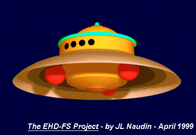
The E.H.D. Flying Saucer
A Tri-Arcuate ship simulation
By Jean-Louis Naudin
created on April 14, 1999 - JLN Labs - Last update April 14, 1999

The E.H.D. Flying Saucer
A Tri-Arcuate
ship simulation
By Jean-Louis Naudin
created on April 14, 1999 - JLN
Labs - Last update April 14, 1999
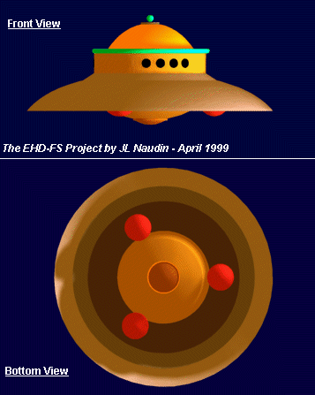
The purpose of this
study is to understand how the shape of electrode (the main
cupola) may increase significantly the differential hydrostatic
pressure thus the lifting thrust applied to the entire ship by
the EHD effect. In a previous computer simulation, I have used a simple arcuate
electrode, in
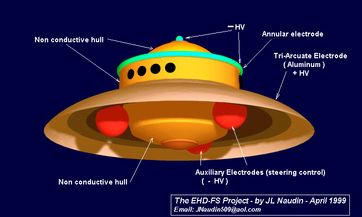
this case the design is now improved with a tri-arcuate
electrode, an annular electrode and also a small spherical
electrode placed on the top.
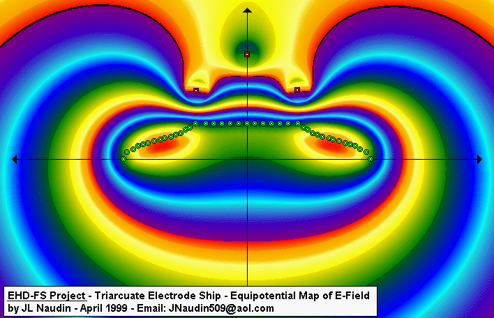
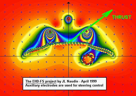
The picture below shows the map of the equipotentials of the
E-Field around the entire ship. The cupola is positively charged
and the other electrodes negatively charged.
The
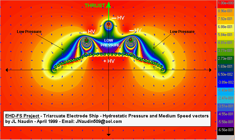
picture below shows the map of the hydrostatic pressure of the
medium such as air or aether, induced by the non-uniform E-Field
around the EHD-FS. You may notice that the hydrostatic pressure
(which can be compared to aerodynamic pressure) is lower on the
upper surface of the tri-arcuate electrode than on the inner
surface of the cupola. This can be compared to a conventional
airplane wing with the extrados ( upper surface of the wing ) and
the intrados ( lower surface of the wing ). This differential
pressure is the direct cause of the EHD-FS lift.
The diagram below shows the curve of this hydrostatic pressure
above the surface of the cupola along the red line. You may see
also the speed vectors (the small blue arrows) of the medium
around the EHD-FS.
Compared to an simple cupola, a tri-arcuate electrode seems to give a better lifting efficiency, because the hydrostatic pressure is distributed on all the upper surface of the electrode as you may notice in the diagram below.

![]() Email : JNaudin509@aol.com
Email : JNaudin509@aol.com
Return to the Advanced Propulsions Researches page