The Poynting Flow Thruster project
Proof of concept
By Jean-Louis Naudin
created on August 18th, 1999 - JLN Labs - Last update December 11th, 2001

The Poynting Flow Thruster
project
Proof
of concept
By Jean-Louis Naudin
created on August 18th, 1999 - JLN
Labs - Last update December 11th, 2001
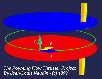
During a charging process of a flat capacitor, the Poynting vector ( S=ExH ) comes from outside the capacitor towards the wire connections, parallel to the surface of the armatures inside the dielectric medium. There is an energy flow directly proportional to ExB. This energy is not provided by the wires but comes from the surrounding space around the capacitor. ( ref: "The Feynman Lectures on Physics : Electromagnetism vol2, Chap: 27-5, fig 27-3" by Addison-Wesley Publishing company. )
The purpose of these series of experiments is :
to check experimentaly the effect of the symmetrical Vs the asymmetrical setup of the wires connected to the capacitor armature,
to check that ionic wind is not the main cause of the resulting thrust.
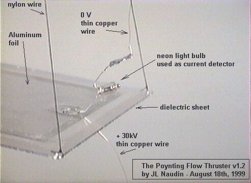
The flat capacitor has been built with a plexiglas sheet ( 180 x130 mm ) used as the dielectric ( thickness = 1.4 mm ). The two sides of the plexiglas sheet have been covered by an aluminum sheet (152 x 102 mm) . The apparatus has been tethered with nylon wires on a specialy balanced equipement. The edges of each armature have been covered by an adhesive tape for reducing the leakage current and some eventual striking. The 30kV DC High Voltage generator has been placed under a wooden table just under the rotation axis. Two thin copper wires have been used for the connection. One thin copper wire has been connected to the zero potential and the other to the 30kV DC High Voltage generator. A small neon light bulb has been connected in serie with the upper wire for showing the current flow during the charging process and the running phase (see the picture below).
Experiments N°1 : ( Geometrical effects testing )
First setup ( symmetrical connections )
In this first setup, the thin copper wires have been connected just in the middle of the capacitor so as to get a symmetrical Poynting flow.
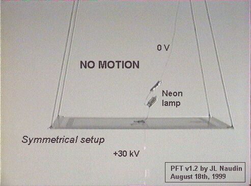
During the charging process, in a flat
capacitor with the wires connected in the middle of the
armatures,
the energy flow (S-Flow) is symmetrical (see the picture above) :
There was NO MOTION of the PFT
Second setup ( asymmetrical connections )
In this second setup, the thin copper wires have been connected at 10 mm from one edge of the capacitor so as to get an asymmetrical Poynting flow .
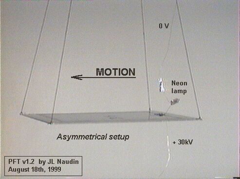
During the charging process, in a flat
capacitor with the wires connected near the edge of the
armatures,
the energy flow (S-Flow) is asymmetrical (see the picture above )
:
The PFT has been SET IN MOTION by the energy flow
See below, the video of the experiment :
RealVideo of the PFT geometrical test (86kb)
( if you don't have the RealPlayer 5.0, you may download it freely at : http://www.real.com/products/player/ )
Experiments N°2 : ( Ionic wind effect testing )
For this experiment, the PFT has been completly enclosed in a big plastic bag, so all ionic effects are kept inside the air bag, this cancels some eventual parasitic thrust due to the motion of the ions (see the picture below).
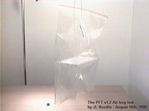
Test results : When the 30kV DC power supply is switched on, the entire apparatus is set in motion in spite of the strong air drag of the plastic bag, this confirms that the observed thrust is not generated by the ionic wind effect.
See below, the video of the experiment :
RealVideo of the PFT Air Bag demonstration (159kb)
( if you don't have the RealPlayer 5.0, you may download it freely at : http://www.real.com/products/player/ )
| TITLE
: Poynting
Vector Probe for Measuring Electrical Power http://patents1.ic.gc.ca/details?patent_number=1264183&language=EN_CA (12) Patent: (11)
CA 1264183
|
See also :
The Poynting Flow Thruster v1.0 the basic experiment.
The PFT v2.0, a spaceship mock-up, towards the deep space.....
![]() Email : JNaudin509@aol.com
Email : JNaudin509@aol.com
Return to the Advanced Propulsions Researches page