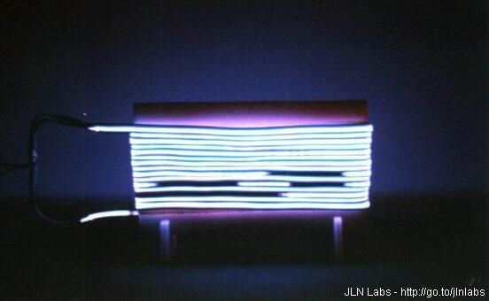

The Glow Discharge Plasma Tests
Advanced Reduced Drag Aircraft project
By Jean-Louis Naudin
created on January
28th, 2000 - JLN Labs - Last
update February 15th, 2000
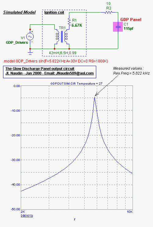
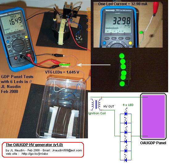
If 6 Leds ( sets in parallel ) are connected in series with the GDP Panels, their brightness is maximum, this proof that a real current flows ( 33mA is required for lighting one led ).
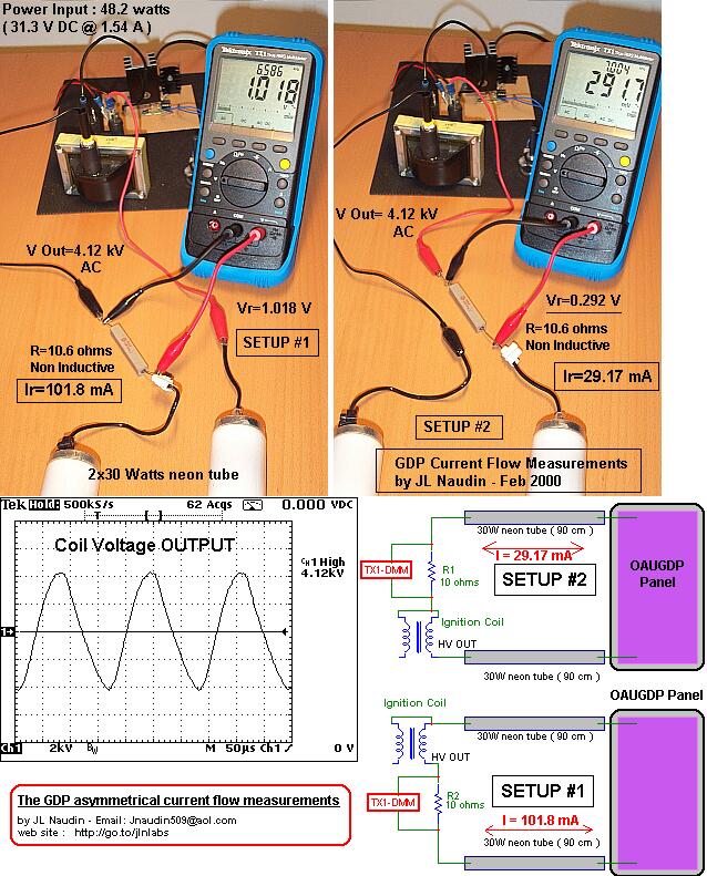
An interesting measurement : The current flow is NOT equal in each branch of the GDP wire.
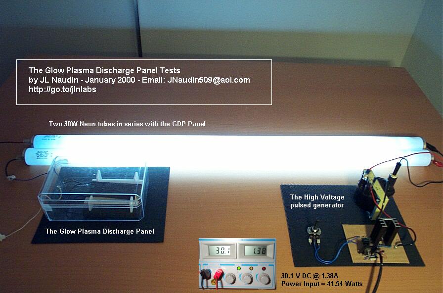
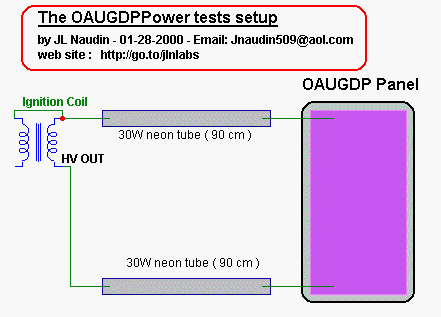
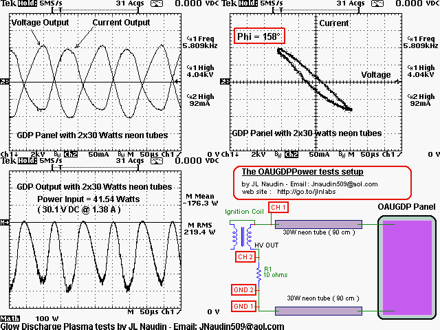
Notes about the measurements (above) :
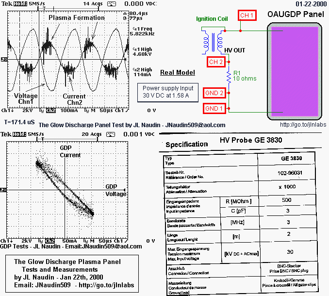
- The upper left scope picture shows the Voltage and the Current curves measured at the GDP output. The Voltage is set at 2kV/div ( in inverted mode ( see the "downward arrow" on the right side of "Ch1", the current is set at 50mA/div ( the current has been measured on the R1 non inductive 10 ohms resistor, with a x10 probe, the scope input channel ratio has been set to 1000mV/A ), the time base used is 50us/div. The right side of the scope picture shows datas measured by the scope itself : on Ch1(Voltage) : freq=5.809 kHz at 4.04kV max and on Ch2(Current) : 92mA max.
- The upper right scope picture, shows the same channels ( Voltage/current in the XY Mode "Lissajous method" ). This is better for measuring the Phase shifting between voltage and current.
- The left
bottom scope picture, shows the third
channel of the scope, this is the Math channel, ( Math=Ch1xCh2 )
this gives in real time the curve of the power flow. The "M"
channel is set to 100W/div, the measured data on the right side
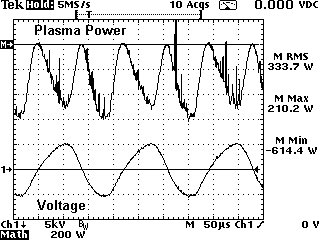
"M Mean" is the Mean power =-173.3 W and the "M
RMS" is the Root Mean Square power = 219.4 W
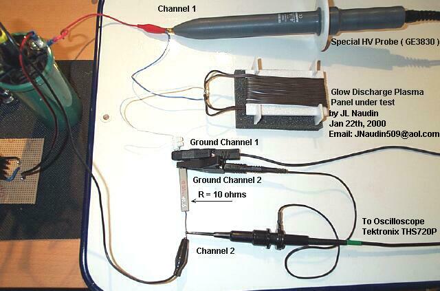
- The right bottom diagram,
shows the setup used during the measurement. ( The DC input power
is 41.54 Watts ( 30.1V DC @ 1.38A ). The voltage is measured with
a special x1000 High Voltage Probe GE3830 ( max working freq: 3MHz)
(see the specs at the top of this page )
For the measurements, I have used a Tektronix oscilloscope THS720P, this is an independently floating and isolated channels scope and it has full floating measurement capability. The THS720P is used completly ungrounded and runs on its own internal batteries.
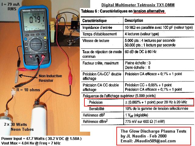
The direct output current from the GDP driver has been also checked with a digital multimeter ( Tektronix TX1 ) with High frequency measurements capabilities on AC voltage ( accuracy 0.002% at 20 kHz (see the specifications sheet below) ). The working frequency was 7 kHz, so this was in the working range of the TX-DMM. The voltage measured current was 0.791 Volt accross a 10 ohms ceramic ( non inductive ) resistor, this gives a current of 79 mA RMS. So, this confirms the previous oscilloscope measurements.
Ignition coil used ( see the picture ):
Manufacturer : Ducellier ( Valeo )
Part ref : 106V 2590836
Coil input :
Inductance : 7.94 mH (measured)
Internal resistance : 3 ohms (measured)
Coil output :
Inductance : 6.5 Henries (calculated)
Internal resistance : 6.67 Kohms (measured)
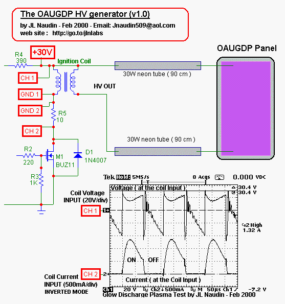
The Voltage and
the Current at the Coil Input has been also measured, the duty
cycle is 50%.
You may see the current pulse during the ON state and the Back
EMF voltage. (see above)
Go to the Next GDP tests
Go to the Glow Discharge Panel construction
You may hear the Glow Discharge Panel sound
Analysis of the GDP sound wave
![]() Email : JNaudin509@aol.com
Email : JNaudin509@aol.com
Return to the Plasma Researches page