The Stacked Lifters experiments
by Saviour ( Europe )

The Stacked Lifters
experiments
by
Saviour ( Europe )
created on
January 16 2002 - JLN Labs -
Last update January 17, 2002
All informations in this page are published free and
are intended for private/educational purposes and not for
commercial applications
|
||||||||||
Hi guys,
Today I have tested and confirmed that vertical stacking works
very efficiently, and is quite easy to implement. This is how I
did it: Starting from top is the anode fine wire, then 40mm below
is the foil, following are a number of stacked foils with the
same 40mm separation between them. No wires in between as the
sharp lower edge of the foil acts as a fine wire. Make the top
part of each foil as smooth and round as possible and the lower
as sharp as possible.
Connect the positive to the top wire and loop the
positive skipping one foil at a time. Do the same for the
negative starting from the top foil and ending at the lower foil.
Preferably you should have an odd number of foils so as to end up
with the highest and lowest foils negative. A 3 stacked basic
lifter lifted 8g whilst a 2 stacked Dupre type lifters (weighing
8g lifted 18g!!, I should add another stack to this, possibly
providing about 28g lift or maybe more. For this
lifter I am using 50mm gaps and about 40Kv or a bit more. Lift is
being calculated by adding weights in a plastic container glued
in the centre. Weights used are pieces of thick wire cut to weigh
0.5g each.
Saviour.
Photos and details, courtesy of Saviour, more photos and technical datas at : http://bel.150m.com/
This page contains a series of experimental lifters or propulsion devices that do not use conventional methods for thrust. These lifters are using the Biefeld-Brown Effect to generate the main thrust to self levitate and are able to lift their own weight and even additional load. They are a "modern versions" of the Townsend Brown Electrokinetic Apparatus, which was patented several years ago and regretably left unoticed at the patent office. A Basic Lifter cell is composed of three Townsend Brown asymmetrical capacitors joined so as to form a triangular unit cell assembly. A triangular structure is far from the optimum shape but due to its simplicity it gives everyone the chance of trying out for himself the potential of this effect. Our aim is to find the best design & materials to construct the most powerful unit cell in the smallest possible space. Please note that these devices use very high voltages (>30KV) and experience in handling high voltage is a must. We are not reponsible if you get killed! All devices have been tested for electromagnetic radiation and found to radiate much less than a mobile phone.
Hints for a good lifter :
Use lightweight foil - the cheapest kitchen foil works fine
Round off horizontal balsa supports with stanley knife before
glueing aluminium
Avoid sharp edges anywhere on foil, or kinks in the wire
Use the finest wire for the top anode wire, preferbly bare or
thin coated copper wire
Use 40mm leg supports leaving a separation between the lower foil
and the table/floor.
Switch off lights and check for purple plasma glow. Eliminate by
smoothing the defective part or coating with hot glue or
araldite. Plasma glow takes off a lot of power that would be
otherwise used as lift.
Hear the sound of the lifter carefully. The sound should be very
smooth flowing jet like wind, with no crackling sounds. If using
a monitor or TV ht output you might hear the 20-22khz tone coming
out from the lifter, but not all of us can hear up to this
frequency. Note balsa is highly flammable, and sparks may trigger
balls of fire reducing your lifter to ashes!
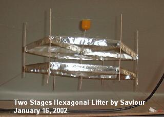
2 vertically stacked hexagonal lifter. 1/2 Kinder egg (0.5g) on top used as container for loads. Air gap between foils is 50-55mm, foil is 20mm each. Note round smooth edge on top side of foil and sharp edge on lower side of each foil. Note that leg supports are not decorative, they are necessary to minimise field effects between the lower edge of the lower foil and the table, even if used on an insulated base.
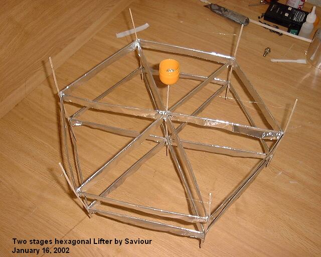
Tried to get a better picture showing the load inside the
capsule and the shadow that shows it lifting (note shadows of its
legs. Sorry I am not yet equipped to produce movie files.
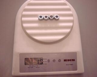
Electronic balance used to measure load which goes in
the Kinder capsule
This lifter weighs 11g and lift an additional weight of 19g including weight of container. Top wire and bottom foil are positive (connected together), the middle foil is negative.
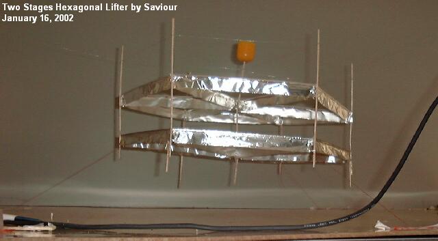
Hexagonal lifter, lifting the 4 nuts. Lifter secured to
table by 3 strings, limiting lift distance to a few cm. I hate
the idea of a lifter falling on my head during the experiments..
You may also note that I have elongated 3 of the lower legs on
this lifter, to obtain better thrust from ground position.
See more photos and technical datas at : http://bel.150m.com/
See also the :
 Lifters builders
and tests feed-back
 ![]()
Return to the Lifters Builders page