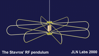

The
Stavros' RF pendulum experiment
An
electromagnetic interaction with the gravity field
Courtesy of
Dimitriou Stavros
By Jean-Louis
Naudin
created on
September 3rd, 2000 - JLN Labs
- Last update September 14th, 2000
This experiment has been done successfully by Dimitriou Stavros from the TEI-Athens, Dept. of Electrical Engineering in Greece.
This is my first attempt of replication of this experiment based on the paper published by Stavros :
" On the pendulum oscillations of a
suspended RF resonant circuit " by Stavros G. Dimitriou
<< Abstract : The
period of the pendulum oscillations of a suspended
electromagnetic resonant circuit formed by quarter-wavelength
transmission line sections is found to be affected by electrical
parameters of the oscillator driving it. Of particular influence
appears to the magntitude of current at resonance, which depends
on the effective quality factor (Q) of the RF tank circuit and
the input driving power. >>
The most interesting fact
observed by Stavros is that " The maximum equivalent reduction of g locally is calculated to -1.3% " :
<< Conclusion : A
gravity - interacting field can be generated electromagnetically
and used to reduce the gravity vector locally. Its implementation
uses the horizontal projections of electric currents, intensified
through almost conventional RF techniques. >>
The full Stavros' paper and the original photos of the experiment can be found in the Jerry Bayles web site : http://www.electrogravity.com/STAVROS/index.html
The RF pendulum experiment tends to confirm the Jerry Bayles theory and research concerning electromagnetic standing waves interaction with the gravity field, see : http://www.electrogravity.com . This experiments is also fully in line with the System-G device and the theory from Prof. Fran De Aquino in Brazil, see : http://members.aol.com/jnaudin509/systemg/index.html
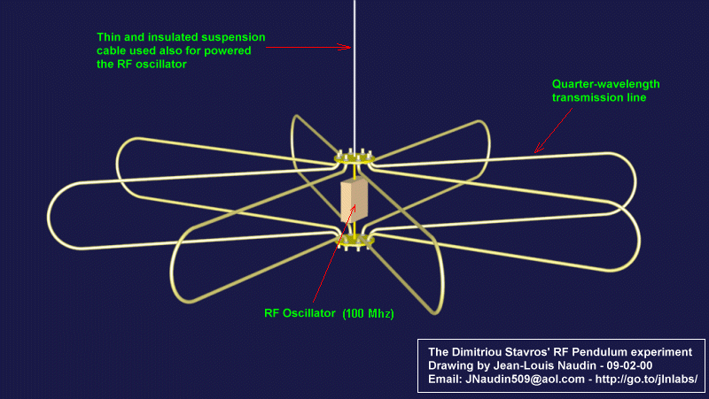
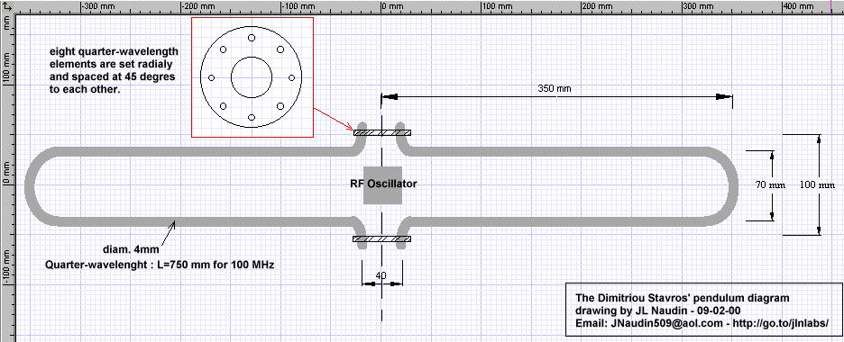
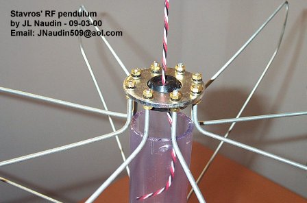
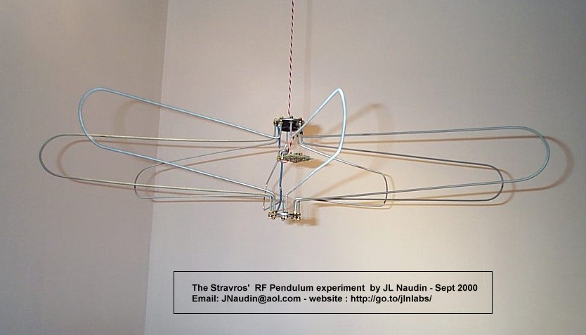
The detailled photo above shows the hanging system and the setup of the quater-wavelength elements placed at 45 degres from each other. You may notice that twisted insulated wires have been used, the RF oscillator was not yet installed.
The photo above shows the Stavros' pendulum with the RF oscillator v1.0 ready for testing
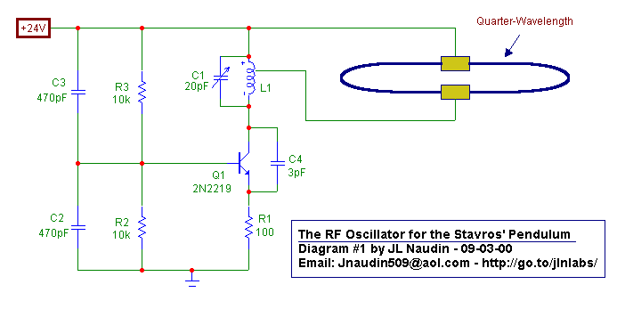
Above, a RF oscillator diagram proposal currently under test.
The DC power input is 0.96 Watt ( 24 Volts, 40 mA ), the estimated RF power output is about 500 mW.
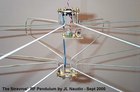
The RF oscillator is now installed, the resonance frequency of the apparatus is 99.5 MHz
FIRST TEST RESULTS : September 4th, 2000
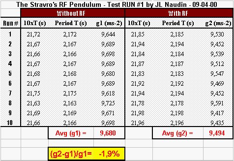
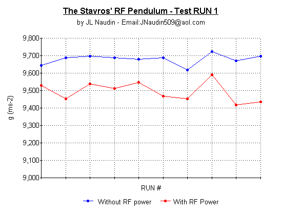
TEST RUN #1 : 10 runs have been performed, each run contains 10 periods (10xT) and the chronometer has been started each time three periods after the initial launch. The pendulum suspension length was 115cm. This length has been measured between the lab ceiling (at the fixing point) and the center of gravity of the pendulum (not at the mounting base point)). The weight of the apparatus is 358 grammes and the apparatus was launched at 30 mm from the vertical position.
This first serie of tests seems to confirm the Prof. Dimitriou Stavros experiment, the gravity field reduction effect mesured is -1.9% when the RF power is sent to the pendulum.
Test RUN #2 ( 09-05-00 ) : A laser beam has been used for measuring the half-period of the pendulum. A BPW34 photodiode has been placed in line with the laser beam and connected to an oscillocope for measuring with accuracy the half-period of the oscillation. ( see the photo of the setup, below ).
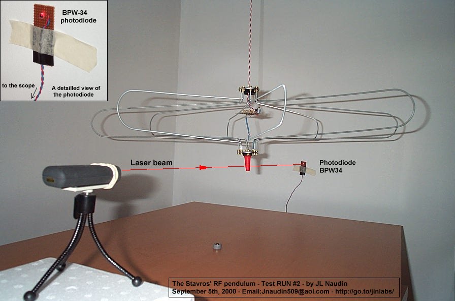
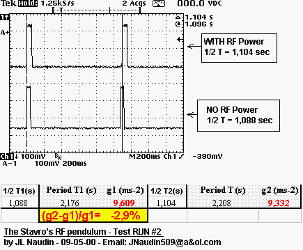
The oscilloscope shows the signal received from the BPW34 photodiode, each pulse is the laser beam interruption signal by the pendulum. So, the duration between each pulse is the time required for the half-period of the pendulum oscillation.
You may notice that :
The gravity field reduction effect mesured is -2.9% when the RF power is sent to the pendulum.
Test RUN #3 ( 09-06-00 ) : The purpose of this test is to check if the period of the pendulum can be altered for different launch angles. So I have measured the half-period with the laser beam apparatus for two different launch positions : 20mm and 50mm. The photo below shows the testing setup. The RF oscillator has not been energized during all this test.
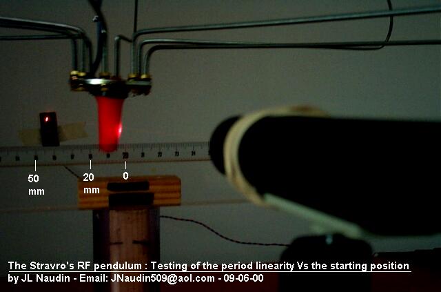
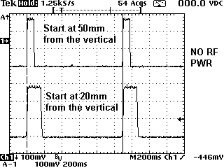
The scope picture shows the half-period measured for these two launch positions, you may notice that the period remains constant for 20mm and 50mm. The pulse width is bigger for 20mm than for 50mm because the oscillation speed is different for these two different angles, but the period remains constant.
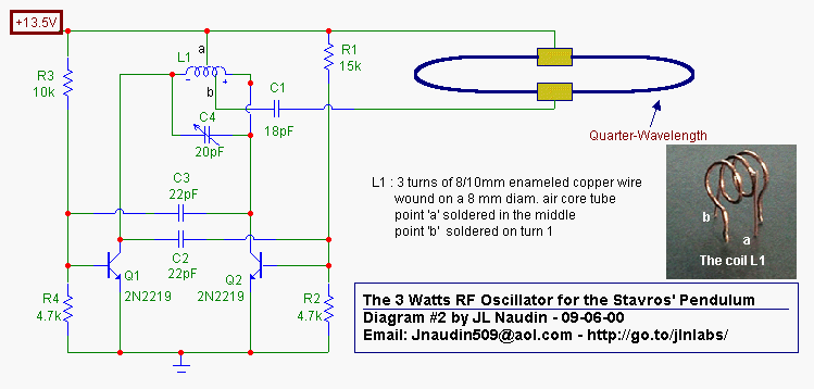
The electronic diagram of the RF oscillator v2.0 (above)
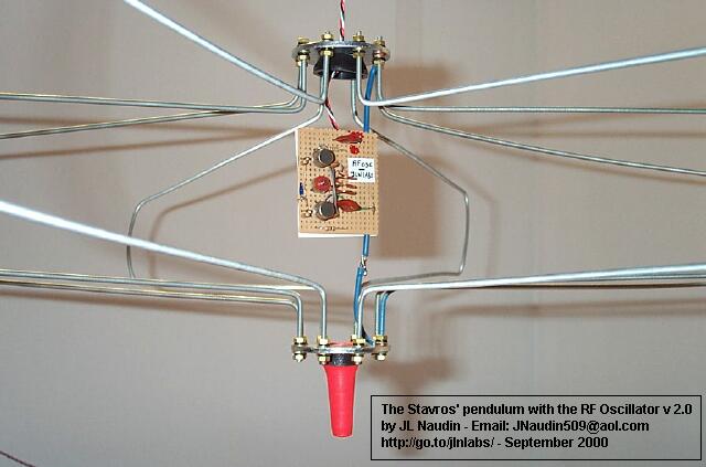
The photo above shows the Stavros' pendulum with the RF oscillator v2.0 installed
Test RUN #4 ( 09-07-00 ) :
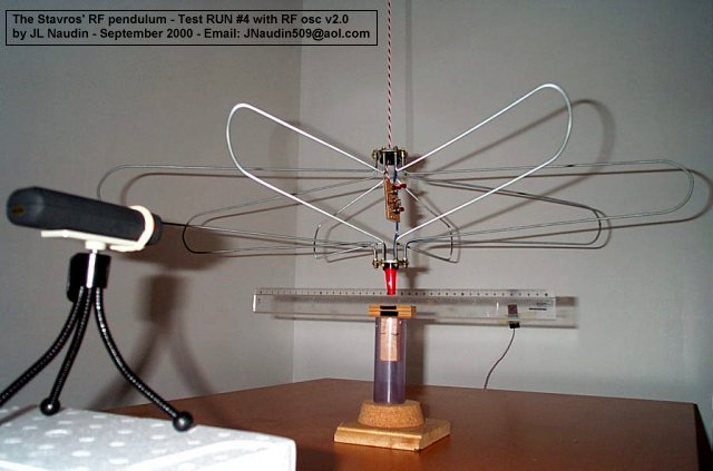
This new test use the latest RF oscillator v2.0, a plastic rule has been added for an accurate launching position ( at : 50 mm )
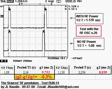
Tests Synthesis ( 09-10-00 ) :
After many tests ( RUN#1 to 4) and different setups of the RF pendulum, today, I can say that :
The effect observed is not so simple
to replicate by anyone, in spite of the simplicity of the
apparatus :
The design must be closer to the original Stavros design
presented in his paper at : http://www.electrogravity.com/STAVROS/index.html
A motion of the apparatus seems
required for observing the effect, there are 2
explanations :
- The basic explanation : Air drag (Cx) modification by
the presence of the RF field,
- The interesting explanation : EM interaction with the
gradient of the gravity field, like the gravitationnal
red-shift when a photon drops from the sky to the center
of the planet.
( the R.V. Pound and G.A. Rebka experiment at the Harvard
university, see the Bekeley Physics Course, volume 1
" Mechanics ", chapter 14 about the "Equivalence
principle"(ed. McGraw Hill )).
The surrounding seems to have no influence on the pendulum period.
The use of electronic scales can create measurement artifacts due to the presence of RF > 100 MHz in the tested apparatus.
When the RF power is sent to the pendulum, it is required to wait few seconds before measuring the period.
Don't forget that the tank circuit is a quarter-wavelength transmission line which must have a High Q factor.
Yet, the Stavros' experiment seems worth to be study and developped. Today, the trick is to identify carefully all the possible artifacts which can affect and hide the real effect originally observed by the Dimitriou Stavros...
I am very grateful to Dimitriou Stavros for the support which he has given to me for a successful replication of this experiment. Many thanks to John Schnurer, Jerry Bayles and Steve Burns for their helpful advices about this field of research.
Good exploration and Best Regards,
Jean-Louis Naudin
Reference documents :
On the pendulum oscillations of a suspended RF resonant circuit by Stavros G. Dimitriou
![]() Email : JNaudin509@aol.com
Email : JNaudin509@aol.com
or send
email to the JLN Lab's eGroup at : jlnlabs@egroups.com if you are a team member.
Return to the Field effect propulsion page