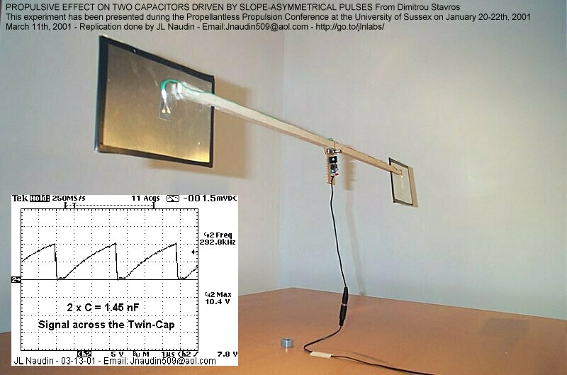
Propulsive effect on two capacitors driven by slope-asymmetrical pulses experiment
PRODUCTION OF DIRECTIONAL THRUST
created on March 4th, 2001 - JLN Labs - March 18th, 2001

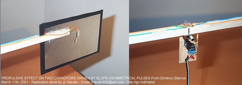
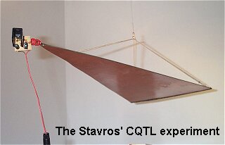
This is the replication of the
Stavros' device for developping a directional thrust and it is
very close to the original setup.
This device has been presented at the
Propellantless Propulsion Conference at the University of Sussex
on January 20-22, 2001
and fully explained in the paper "Efforts in
developing upward and directional thrust" by Stavros G. Dimitriou
| Characteristics
of the tested apparatus Total
measured capacitance of the two capacitors
: 1.45 nF Some advices : The device is very
sensitive to the air motion in the
room, cautions must be taken before each test run :
|
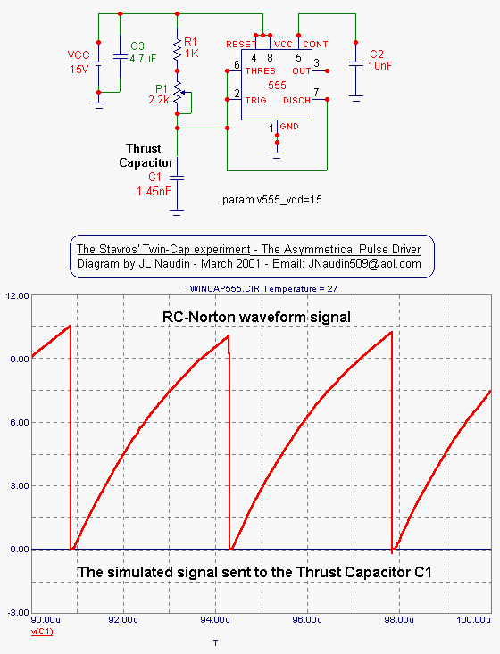
The original Stavros' diagram has
been used for this experiment
The measured signal shape (below) sent to the Twin-Cap (C1) is
fully in line with the RC-Norton waveform simulated above.
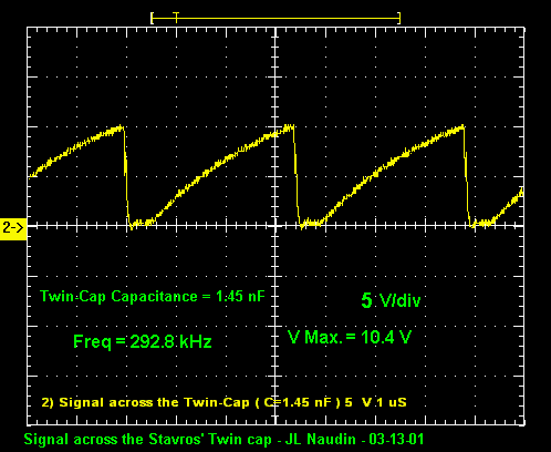
The Real signal measured across the Twin-Capacitor
" With the measured capacitance of 1.45 nF
for the two capacitors, the fundamental frequency of the waveform
should be ![]() = (1/(2*pi*1.45nF*376.7
ohm)) = 291.378
kHz (theoretically) or close to
that as possible in practice ( Z0 is the free-space impedance (
see formula (11)
). A peaking of
the output thrust is observed when this condition is fullfilled."
- Stavros Dimitriou
= (1/(2*pi*1.45nF*376.7
ohm)) = 291.378
kHz (theoretically) or close to
that as possible in practice ( Z0 is the free-space impedance (
see formula (11)
). A peaking of
the output thrust is observed when this condition is fullfilled."
- Stavros Dimitriou
See the Videos of the experiment ( below )
Download the Video of the test ( size 377 kb )
Download the Video of the test ( size 264 kb )
To see thess videos, the free
downloadable RealPlayer is required ![]()
 The
Stavros' Circular Transmission line experiment
 Efforts
in developing upward and directional thrust
by Stavros G.
Dimitriou
Return to the Field Effect Propulsion page