updated 6th of October 97
Proof of overunity efficiency in a R-L circuit with switched inductivities
by J.L.Naudin, W.D.Bauer and S.Hartmann
![]() 1.version 30.9.97, 2.enlarged version 5.10.97
1.version 30.9.97, 2.enlarged version 5.10.97
updated 6th of October 97
Abstract:
In this article we prove overunity efficiency of a simple R-L test
circuit experimentally and theoretically.
It must be noted, that this test circuit was tried using a bifilar
coil, but used as 2 normal in series
wired coils and NOT in BIFILAR NON-INDUCTIVE mode !
As our theory calculation uses 2 normal coils, where the flux does NOT interact, it is advised, that you should just use 2 normal coils which are not magnetically coupled , if you want to try this experiment yourself !
Experimental section:
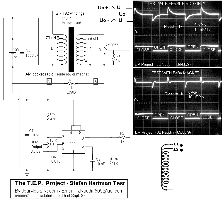
Following ideas of Fred Epps and Stefan Hartmann (1) using
bifilar coils for overunity experiments one of the authors (J.L.N.)
built up the following circuit which showed a remarkable waveform at
the load resistor R 8 of the circuit.

Calculation of spent energies:
The overunity efficiency of this current at the load resistor can be
seen as follows:
Because the circuit is a R-L circuit principally we can decribe the
waveform of each half cycle in the oscillogram at R 8 by

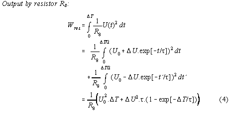
Therefrom we can calculate the current in the cycle
![]()
Therefrom follows:


Hints for possible improvements of efficiency:
1) It is useful to choose ![]() so that
so that ![]() becomes a maximum which can be found by extrapolation
by solving the equation
becomes a maximum which can be found by extrapolation
by solving the equation ![]() . Therefrom we get the condition for maximum efficiency
. Therefrom we get the condition for maximum efficiency
![]() . Under this
condition the possible maximum efficiency is
. Under this
condition the possible maximum efficiency is

2) The voltage jump due to the switching should be maximized.
Therefore the switched coil should be big and the switching of the
coil as fast as possible. Therefore, the parasitic capacity of the
coil should be reduced as far as possible by winding the coil more in
heigth than in length like flat Tesla coils which are the extremum of
this design.
3) The influence of the timer should be decoupled as far as
possible
4) Up spikes enhance efficiency, down spikes depress it. Therefore,
the peak of the down spike could be lowered by a slowly switching on
of the transistor by an appropriate slowly voltage ramp at the basis
of the transistor or FET.
Theoretical section: (uses 2 normal
aircore coils, not coupled magnetically !)
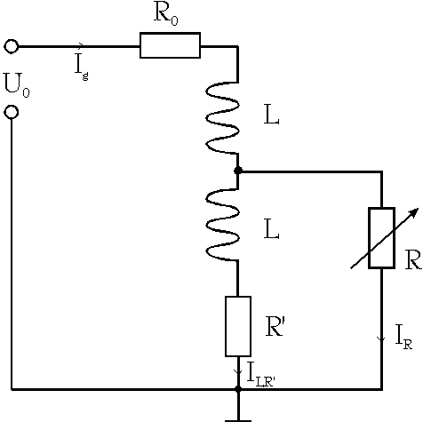
In principle the circuit under consideration is a simple
R-L circuit which is represented in a simplified form in the picture
below. The definition of the variables of analysis below can be taken
therefrom

The differential equation of this circuit is
![]()
Because ILR' = Ig - IR the last equation can be written
![]()
The left side of the last equation is the inhomogenic part of the
differential equation because it can be set by the basis of the FET
or transistor represented in figure above as variable resistor R. We
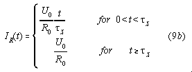
assume for demonstration purposes that IR will be set by
FET in the opening phase so that (with ![]() as switching time)
as switching time)

for the closing phase holds

Furthermore we choose R' so that R'.I
LR'<<U0 , so that R'.I LR' can
be neglected against U0 .
Therefore equation (8) can be reduced to a normal R-L circuit
subjected to rectangular voltage spikes of heigth with ![]()
![]()
The solution of this problem is solved in the most standard textbook of electronics and has a form which resembles exactly the pictures from scope shown above.
Conclusion:
In order to fulfill the law of conservation of energy (first law
of thermodynamics) energy must be coming into the circuit at the
switched coil.
If this additional energy is converted from surounding-heat then a
cooling down of the coil and ferrite should be measurable !
But problems arrive with this explanation if we have aircore coils in
vacuum at very low temperatures. A least there other possibilities of
explanation like Zero Point Energy (ZPE), G-strain energy, aether or
similar concepts have to be taken into account.
Bibliography:
(1) see at mailing list freenrg-l at
www.eskimo.com/~billb in
the archives for July-September 1997
(2) See the TEP development at Jean Louis Naudin´s site at: members.aol.com/jnaudin509
(3) See the latest TEP pictures here at the site:
www.overunity.de/tep
If you need more informations or if you have any suggestions send us
your Feedback
![]() Emails :
J.L.
Naudin ,
W.D.Bauer, S.Hartmann
Emails :
J.L.
Naudin ,
W.D.Bauer, S.Hartmann