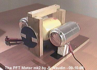
The PFT Motor mk2
The Poynting Flow Thruster project
By Jean-Louis Naudin
created on September 11th, 1999 - JLN Labs - Last update April 24th, 2001

The PFT Motor mk2
The Poynting
Flow
Thruster
project
By Jean-Louis Naudin
created on September 11th, 1999 - JLN
Labs - Last update April 24th, 2001
The PFT Motor mk2 uses two asymmetrical capacitors for generating a continuous rotation of the rotor at high speed. The rotor is composed of a dielectric ( a common plastic ) cylinder with an aluminum sheet fixed in the inner surface, this is the rotating armature of the cylinder capacitor. Two aluminum cylinders ( length: 115mm, diam.: 65mm ) have been used as the fixed armature of the capacitor. The measured capacitance is about 14pF. One aluminum cylinder has been connected to +28kV DC and the other to the ground (OV).
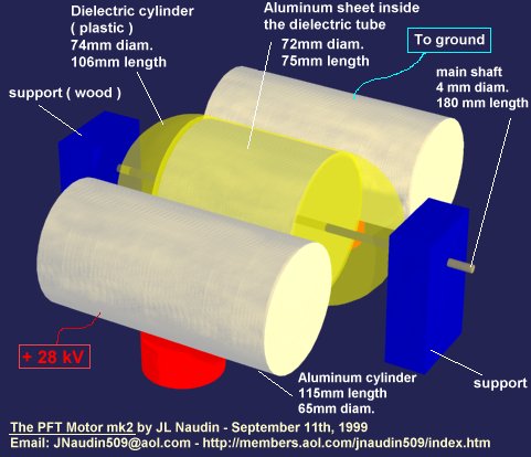
With the rotor blocked, the leakage current was only 1uA, so the coronna effect was insignificant and this shows clearly that this motor is not a coronna motor. Some other tests have been done for checking if the E-Field induction effect is the source of the high speed rotation ( see : Induction effect testing ). The tests has showed that the high speed rotation wasn't generated by the E-Field induction effect.
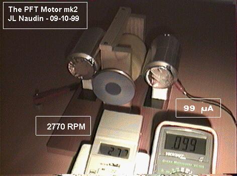
The PFT Motor mk2 turns at high speed : 2770 RPM with only 99uA. The PFT Motor mk2 has no brushes and it can run for a long time.
The PFT Motor mk2 concept will be soon used in a new PFT spacecraft engine design.
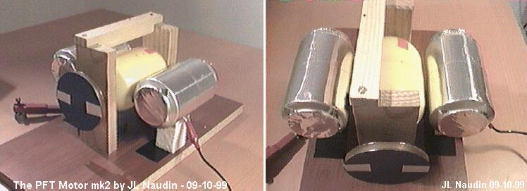
The gap between the cylinders and the rotor is about 1.5mm. You see also the aluminum wheel with two white marks for measuring the turn speed with an optical tachometer.
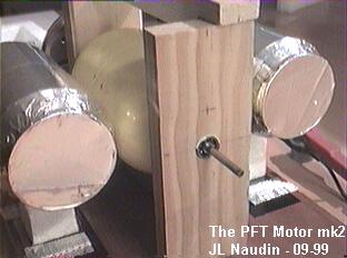
The 4mm steel shaft has been mounted with two 12mm ball bearings fixed on the wooden supports (see the picture).
Experimental setup: The PFT motor mk2 has been tested successfully powered with an electronic High Voltage DC generator, the current has been measured with a digital multimeter and the turn speed with an optical tachometer. The motor doesn't start itself, a gently push is required for inducing a rotational asymmetry in the E-Field and thus a continuous asymmetrical S-Flow :
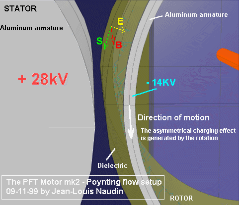
Spinning of asymmetrical E-fields is the main key of this motor
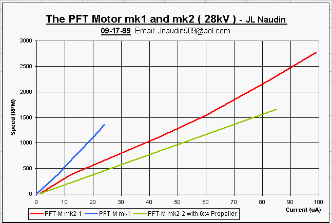
See also : The PFT Motor power I/O measurement diagrams.
You may see the video of the PFT Motor mk2 test, below :
RealVideo of the PFT Motor mk2 demonstration (346kb)
( if you don't have the RealPlayer 5.0, you may download it freely at : http://www.real.com/products/player/ )
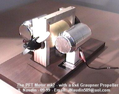
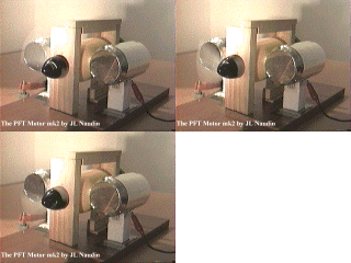
The PFT Motor mk2 is fully capable to run at high speed with a propeller ( a 6/4" pitch, 15/10 cm ) Graupner
Additional notes : "In March 1971, Dr. Oleg Jefimenko proved that a wire held aloft by a ballon at 1200 feet altitude would provide 70 watts of high-voltage power to an electrostatic motor (an improved version of the Franklin motor) for as long as the ballon stayed at that altitude. The wire was a high impedance conductor; and the motor ran at 12,000 rpm or about 200 pulses per second. The motor was a small capacitance device; and had it been run at the impossible rate of 20,000 pulses per second (120,000 rpm) it might have drawn down some 7000 watts of free power !!" ( from the "Vindicator Scrolls" volume one by Stan Deyo, publishers: West Australian Texas Trading)
You may see the video of the PFT Motor mk2 with the propeller in action, below :
RealVideo of the PFT Motor mk2 demonstration (112kb)
( if you don't have the RealPlayer 5.0, you may download it freely at : http://www.real.com/products/player/ )
See also :
A sucessfull replication of the PFT motor by Neil McPherson
The PFT Motor mk1, the basic design.
Variations on the PFT Motors of JL Naudin by Dave Squires
![]() Email : JNaudin509@aol.com
Email : JNaudin509@aol.com
Return to the Advanced Propulsions Researches page