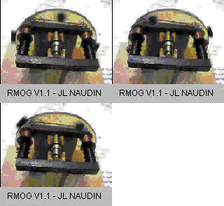

The Greg Watson RMOG
created on 10/23/97 - JLN Labs - last update on 02/21/99
TEST BY Jean-Louis NAUDIN (10/22/97)
Note from JL Naudin (first test of 10/23/97) : This RMOG has been built as indicated by Greg Watson, but today, unfortunately my actual version STOPS QUICKLY after a good spin with my hands.
Additional notes from Greg Watson :
Suj :	RMOG Builders
Date :	24/10/1997 03:14:03
From:	gwatson@microtronics.com.au (Greg Watson)
Resent-from:	freenrg-l@eskimo.com

HI Jean-Louis, Ken and others,

Several points you might find helpfull,

1) Use weak magnets.

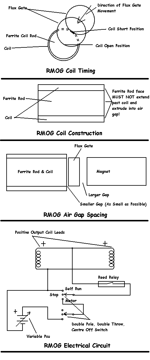
2) Use about 4-6mm spacing on the flux gate to magnet side and as
close as possible on the flux gate to coil side.

3) Magnet spindown with the coils open should be small.

4) Connect a variable power supply in series with the coils and reed
relay.  Polarity to generate a same pole face in the gap as the
magnet.  Check for how much voltage you need to get the "Motor" to
run.  Then alter spacings in the gap to get lower drive voltages.  RPM
is NOT the goal, its low drive voltage.  The lower the drive voltages,
the higher the efficiency.

5) Connect the coils in parallel.  First CHECK with a scope that the
voltages are in phase.

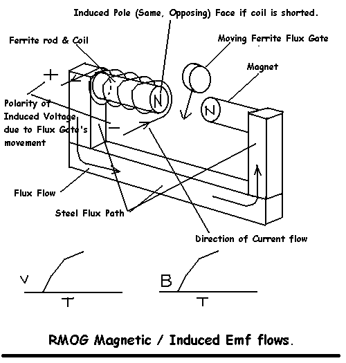
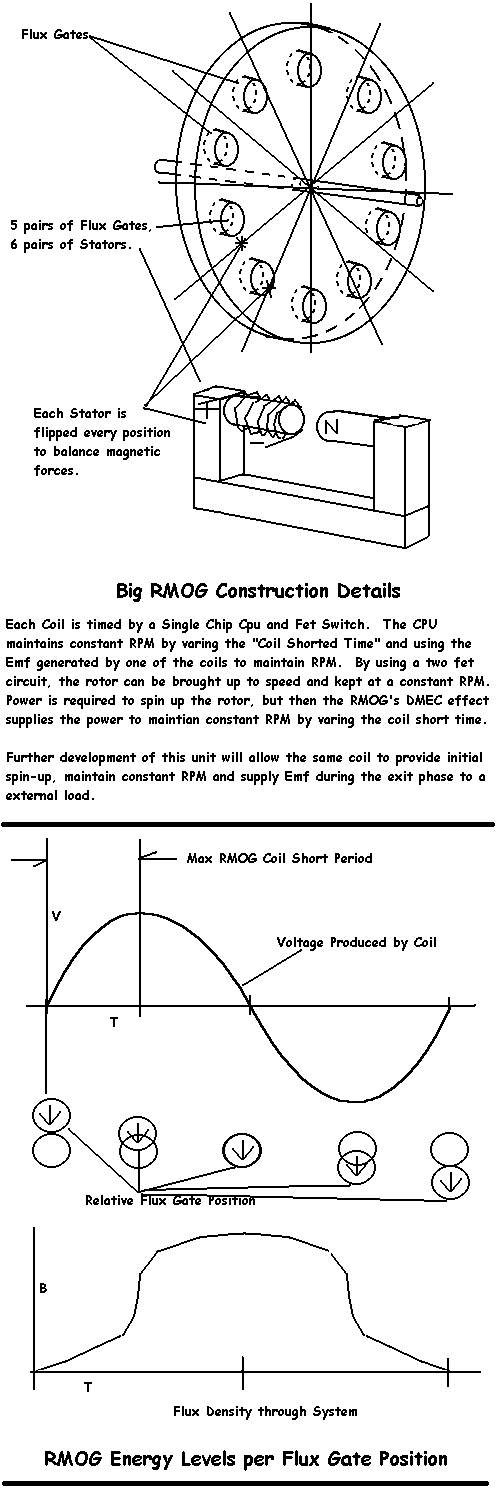
6) The coils should only be energized / shorted for 7.2 deg or 5mm of
flux gate travel.  Its very important that the coil open point be
correct.

7) Remember that the perspex disc will cause high thrust loads on the
bearing as the flux gates move across the magnets.  This could be a
point of high energy losses and must be working well.

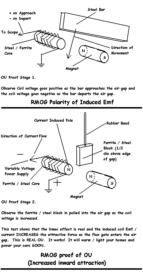
8) Bypass the reed relay and with the coils powered from the supply,
you should feel the flux gates being repelled away from the centre of
the magnets just like the suggested 2 magnet and ferrite experiment I
posted on the RMOG site.

It does work.
Best Regards,
 Greg Watson
New tests by JL Naudin,on the RMOG V1.1 (10/24/97)
(click here for the full AVI video movie of the RMOG V1.1 ( this is the 6V DC powered version))
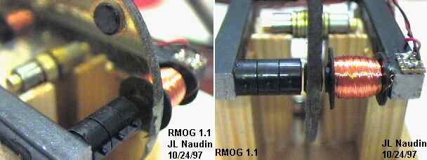
Some details of my RMOG V1.1
Technical specifications of the JLN's RMOG 1.1 :
As Greg has said above, I have improved my RMOG V1.0 by reducing mechanical frictions, I have put in series with the ILS switch and the coils (connected in parallel) a 6 Volts DC power supply. The RMOG V1.1 turns now at 150 RPM (see the video).
The ferrite flux gate must be very close to the coils (1mm), thus the magnets must be at least 4 mm far from the flux gate. The most difficult is to have a frictionless rotation in spite of the high trust load on the main axis due to the magnets attraction.
I suggest you to let your RMOG device working in powered mode for a "running in" at least 12h long, before the first try in self-powered mode. During this "running in" period, I suggest you to put a 1N4007 diode accross the RMOG's coils to protect you ILS switch from the backemf spike, don't forget to remove this diode after this "running in" phase. This diode destroy the DNMEC effect used in the RMOG's device .
Towards a free device ? ....Today, this device need few electrical power for running....
Technical informations from Greg Watson(10/25/97)
RMOG RealVideo movie with JL Naudin's explanations (click here)
( if you don't have the RealPlayer 5.0, you may download it freely at : http://www.real.com/50/index.htm )

Email : JNaudin509@aol.com
Return to the Permanent motors page