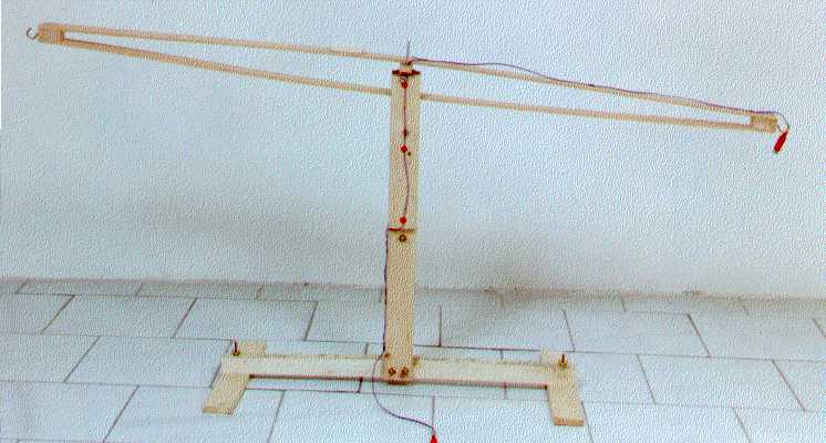
The wooden balance used by Stavros Dimitriou for measuring the weight change with his RF pendulum device
The
Stavros' Wooden Balance
An
electromagnetic interaction with the gravity field
Courtesy of
Dimitriou Stavros
By Jean-Louis
Naudin
created on October
15th, 2000 - JLN Labs - Last
update October 15th, 2000
Sujet : wooden balance
Date : 15/10/00 00:54:44 Paris, Madrid (heure d'été)
From: xxxxxxxxx (Stavros Dimitriou)
To: JNaudin509@aol.com
Dear Jean-Louis
Here is the wooden balance I have used.

The wooden balance used by Stavros Dimitriou for
measuring the weight change with his RF pendulum device
The pivot screws provide a minimum of
turning resistance and at the same time serve as contacts for the
supply rail to the experiment's end. The
screws pass through a copper ring (shown brown) each, which
provides contact to the wire leading to the experiment end of the
beam.
The still contacts, on the top of the support of the balance are
made of two piecec of bronze, with a small inward bump in them,
to accommodate the tip of the corresponding pivot screw.
The pivot screws permits adjusting the center of weight of the
beam. They also adjust the horizontal correctness of the beam.
Any little discrepancy of balance is set by using a small
trimming wait. I used a school rubber in the photograph. ( It can
be seen where it should not have been in one of the photos of the
beam! ).
The counterweight is usually a 500 ml plastic bottle of some
refreshment, filled with sand to the appropriate weight. The
bottle hangs from its tap, which has been punched through in two
places.
A 5 cm loop of thread through these holes serves to hung the
counterweight bottle.
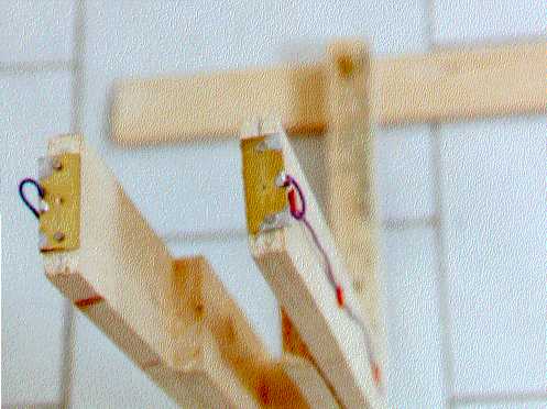
The supports, see the contacts
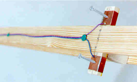
The Beam contacts
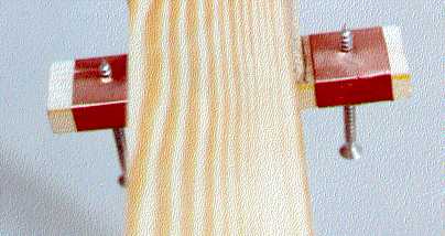
The pivots screws
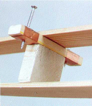
The spacers in the beam ( see the pivots screws )
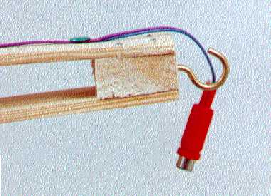
The beam ends
Sensitivity: About 0.1 gram for 1 mm
deflection at a beam load of 0.8 kg in total. The sensitivity
deteriorates with the increase of weight, as the screw tips bite
into the bronze contacts. Any better ideas of pivoting are most
welcome.
Dimensions: beam:122 cm, excluding the hooks.
Beam separation at center: 5.2 cm
Beam width: 3.7 cm
Beam wood thickness 5mm
Screw spacing: 6.5 cm
Support height: 52 cm
Bronze contacts: 1 by 3 cm by 0.5 mm
Support feet: 33 cm long
Support foot spacing: 57 cm
Feet connecting beam: 3 by 3 cm by 61 cm
The twin beam arrangement and the adjustable pivoting are
credited to Dr David King of the University of Manchester.
Best Regards
Stavros
Return to the Field effect propulsion page