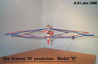

The
Enhanced Stavros' RF pendulum
An
electromagnetic interaction with the gravity field
Courtesy of
Dimitriou Stavros
By Jean-Louis
Naudin
created on
September 3rd, 2000 - JLN Labs
- Last update October 15th, 2000
One of the major parameter is the Q factor of the tank circuit. So, I have decided to rebuild a new tank circuit with copper wires ( previously, I had used Nickel ) and brass for the mounting base for reducing the resistance of the circuit and thus increasing its Q factor.
Dimitriou Stavros has given me some very helpfull advices (see below) and he has also suggested me to update the setup of the 1/4 waves transmission lines with a new design, see : A new RF pendulum model
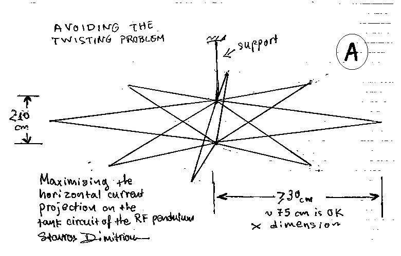
The RF pendulum Model "A" from Dimitriou Stavros
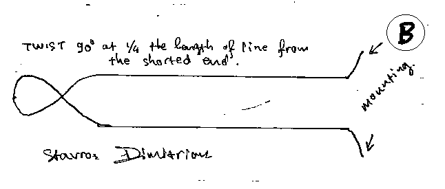
The design of one 1/4 wavelength transmission line for RF pendulum Model "B" from Dimitriou Stavros
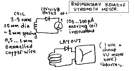
How to build a basic field strength meter for tuning the apparatus at resonance
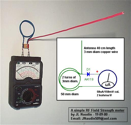
A picture and the diagram of my RF Field strength meter that I have used for the tuning
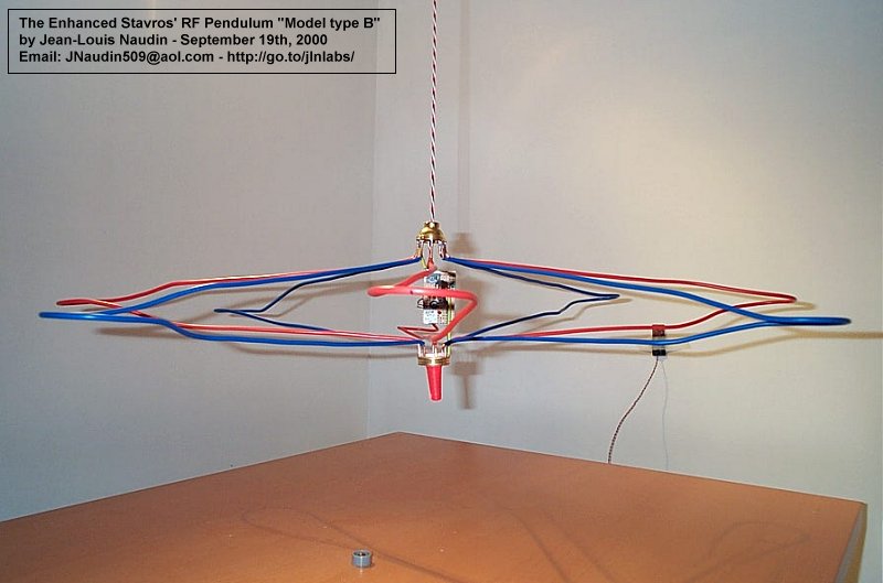
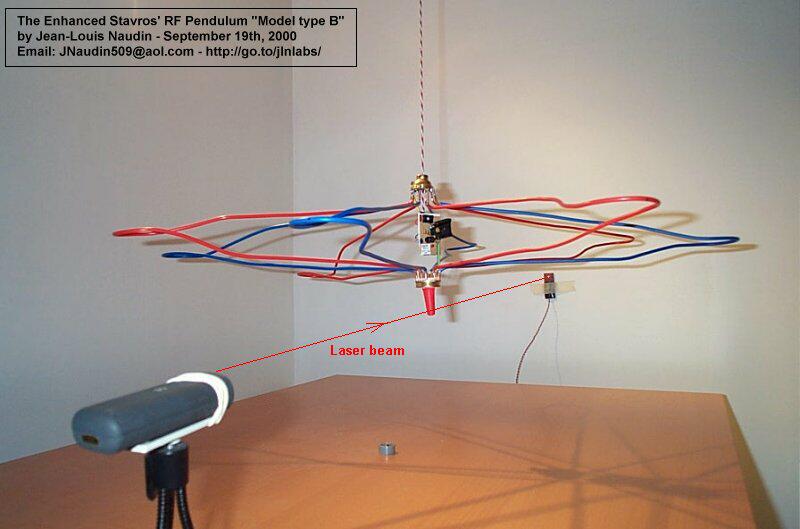
The New Stavros' RF pendulum Model "B" ready for testing.
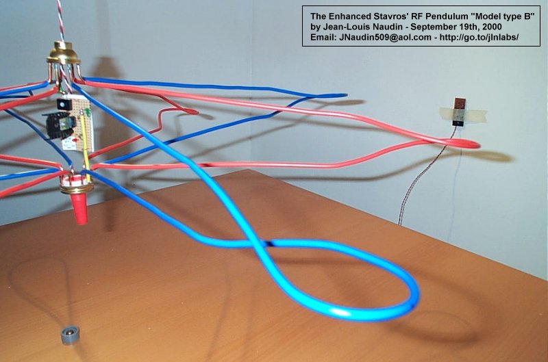
A close view of the twisted 1/4 wavelength transmission lines, I have used copper wire ( 4 mm diam. plastic insulated )
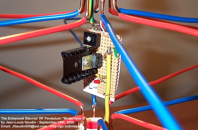
A detailled view of the VHF oscillator ( model v3.0 see the diagram at : stvrfpnd2.htm )
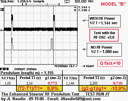
Test RUN #7 ( 09-19-00 ) : The Quality factor of the transmission line has been measured at the resonance frequency Fo = 83.1 MHz :
Q factor = Fo / ( F2-F1 ) = 83.1 / ( 89 - 80.73 ) = 10.05
Now, the Q factor has been significantly improved comparing to the previous version. The tuning of the resonance frequency is a bit more accurate and the power output more stonger. I have also noticed that the heat sink of the BD827 transistor is only warm and doesn't become hot, this confirms that the efficiency of the circuit has been improved by the increase of the Q factor. The pendulum suspension length was 1,155m. This length has been measured between the lab ceiling (at the fixing point) and the center of gravity of the pendulum (not at the mounting base point)).
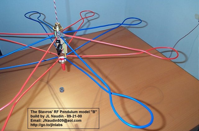
With the twisted loop of the transmission lines more closed, the Q factor is equal to 34
Comments from JL Naudin : The use of an electronic scale for measuring some eventual weight modifications isn't recommended. My full electronic scale is jammed and unusable at 2 meters far from the apparatus by the strong RF power generated which produces electromagnetic interferences ( EMI ). The Q factor and also the shape of the transmission lines seems to have a major role in the effect. The origin of the effect observed here is not yet fully understood ( EM interaction with gravity field, air drag effect on the wired frame.... ) and need further investigations...
---------------------------
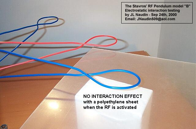
Tests RUN #8 ( 09-24-00 ) : The purpose of these tests is to check if the surrounding material may be the origine of the observed phenomenon. So, I have conducted 3 different tests :
1) Electrostatic influence test : I have checked if the proximity of a polyethylene sheet placed below one of the transmission line is able to generate some electrostatic parasitic thrusts by sending the RF power pulses with a period of 2 seconds. There is no observable motion of the apparatus.
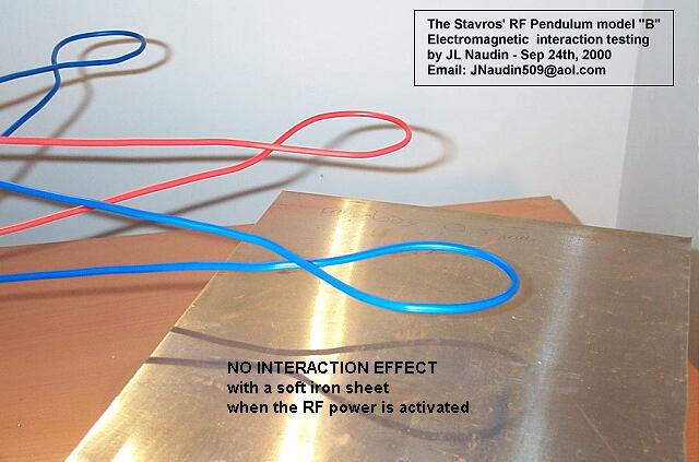
2) Electromagnetic influence test : I have checked if the proximity of a soft iron sheet placed below one of transmission line is able to generate some electrostatic parasitic thrusts by sending the RF power pulses with a period of 2 seconds. There is no observable motion of the apparatus.
3) Magnetic influence test : I have checked if the proximity of 3 strong Neodynmium stacked magnets (27 MGoe each) placed below one of transmission line is able to generate some electrostatic parasitic thrusts by sending the RF power pulses with a period of 2 seconds. There is no observable motion of the apparatus.
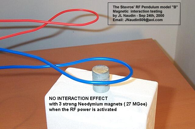
Comments from JL Naudin : These 3 simple interaction tests tend to confirm that the surrounding ( wall, ceiling, table... ) are not able to be the origin of the phenomenon observed here.
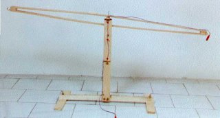 The Stavros' wooden
balance apparatus used for the model "B"
I am very grateful to Dimitriou Stavros for his support and the helpful advices which he has given to me for a successful replication of this experiment.
Reference documents :
On the pendulum oscillations of a suspended RF resonant circuit by Stavros G. Dimitriou
Back to the previous RF pendulum tests
![]() Email : JNaudin509@aol.com
Email : JNaudin509@aol.com
or send
email to the JLN Lab's eGroup at : jlnlabs@egroups.com if you are a team member.
Return to the Field effect propulsion page